
Superalloy repair methods

a superalloy and repair method technology, applied in the direction of manufacturing tools, welding/cutting media/materials, welding apparatus, etc., can solve the problems of thermal-mechanical fatigue, interference with the optimal operation of the engine, and wear and damage of the components of the gas turbine engine, so as to increase the resistance to thermal-mechanical fatigue

Inactive Publication Date: 2007-03-01
UNITED TECH CORP
View PDF17 Cites 45 Cited by
  • Summary
  • Abstract
  • Description
  • Claims
  • Application Information

AI Technical Summary

Benefits of technology

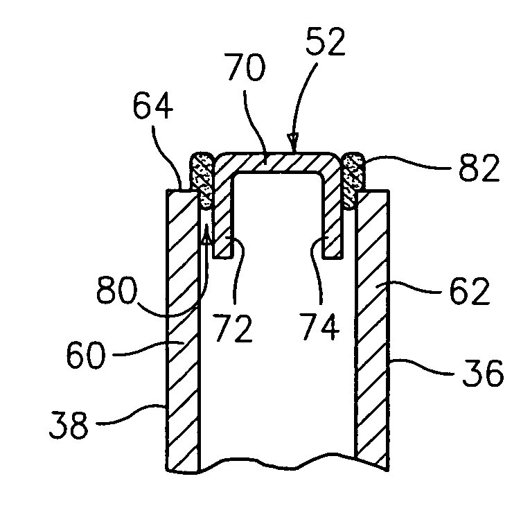
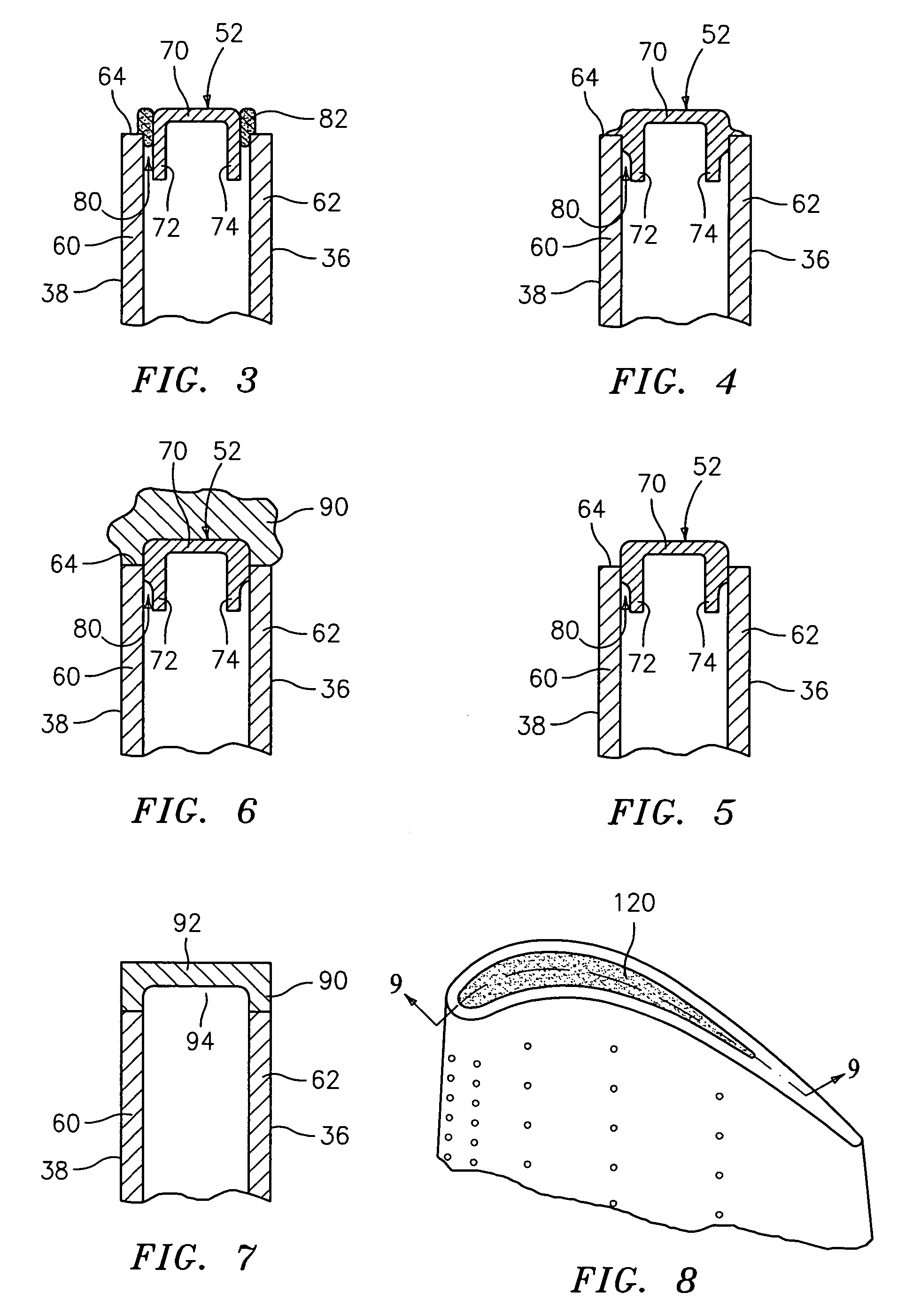
[0010] The portion may comprise a first portion inserted within a pre existing portion of the internal space and a second portion. The component may have previously lacked said internal space. The adding may comprise diffusion brazing using a powdered material comprising a mixture of first and second component powders, the second powder being a majority, by weight, of the powdered material and the first powder acting to infiltrate the second powder upon melting of the first powder. The first powder component may include in its composition a quantity of a melting point depressant substantially in excess of that in the second powder. The first and second component powders may be present in a mass ratio of between 1:10 and 1:2. The first component powder may have at least 2.5% boron and the second component powder may have less than 0.5% boron. The first component powder may have at least 2% boron and the second component powder may have less than 1% boron. The first and second component powders may be nickel based. The internal space may extend to a damage site from which the component has lost first material. The method may further comprise removing additional material at least partially from the damage site to create a base surface. The adding of the material may add the material atop the base surface at least partially in place of the first material and the additional material. The material may in major part replace said first material. The blocking

Problems solved by technology

The components of gas turbine engines are subject to wear and damage.
Even moderate wear and damage of certain components may interfere with optimal operation of the engine.
Wear and damage may interfere with their aerodynamic efficiency, produce dynamic force imbalances, and even structurally compromise the worn / damaged parts in more extreme cases.
Such techniques have offered a limited ability to build up replacement material to restore an original or near original cross-section.
However, the structural properties of the replacement material may be substantially limited relative to those of the base material.
For build-up repairs, usually only a partial isothermal structure is achieved due to limitations in diffusion time relative to the required diffusion distances.

Method used


Image

  • Superalloy repair methods
  • Superalloy repair methods
  • Superalloy repair methods

Examples


Embodiment Construction

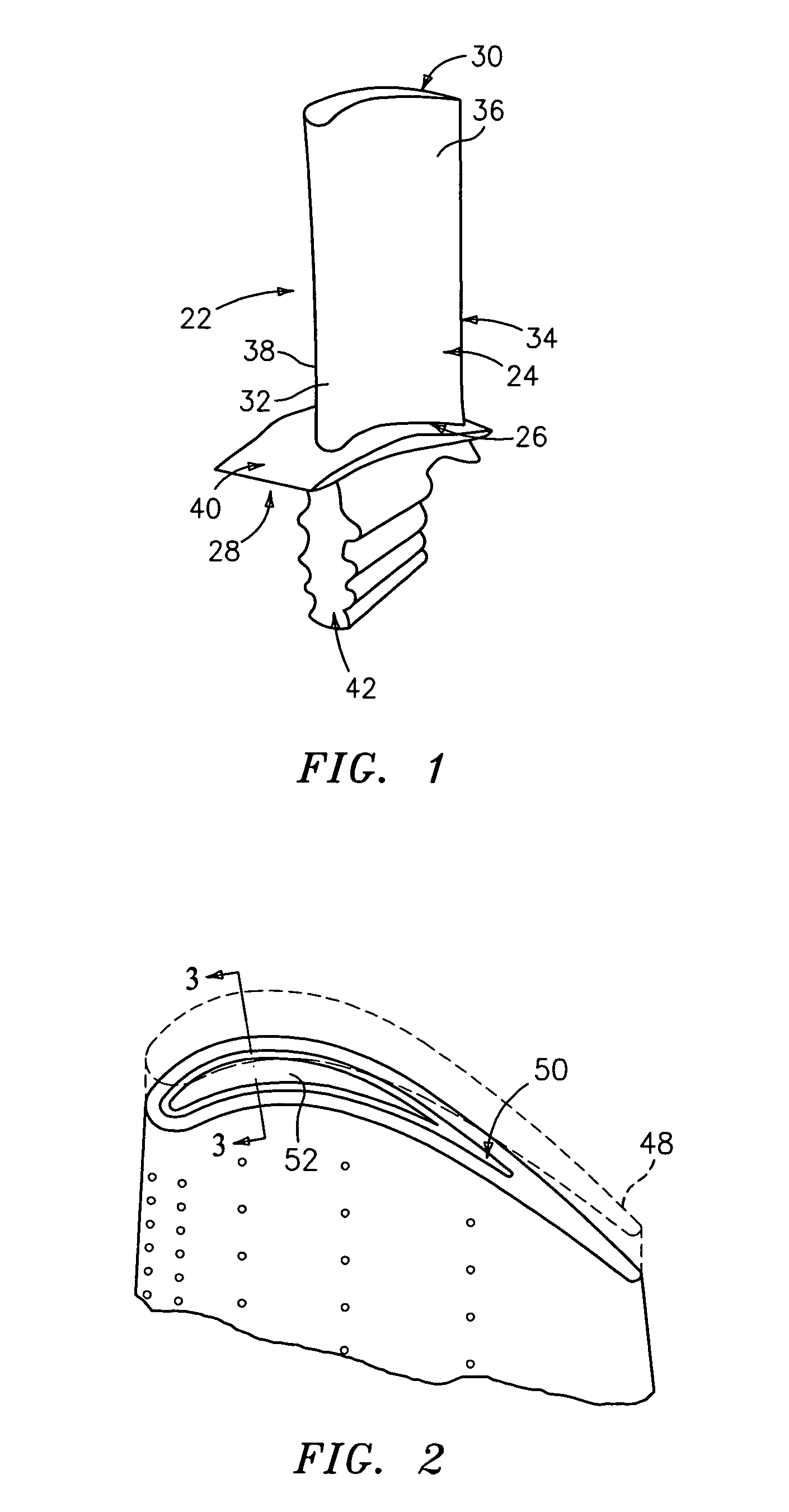
[0026]FIG. 1 shows a gas turbine element (e.g., a gas turbine engine turbine blade 22). The exemplary blade 22 includes an airfoil 24 extending from a root 26 at a platform 28 to a tip 30. The airfoil has leading and trailing edges 32 and 34 separating pressure and suction sides 36 and 38. The platform 28 has an outboard portion 40 for forming an inboard boundary / wall of a core flowpath through the turbine engine. A mounting portion or blade root 42 depends centrally from the underside of the platform 28 for fixing the blade in a disk of the turbine engine. Optionally, all or some portion (e.g., the platform 28 and airfoil 24) may be coated. A cooling passageway network (not shown in FIG. 1) may extend through the blade from one or more inlets in the root to multiple outlets along the blade sides, edges, tip, and / or root. Exemplary blades may be made from nickel- or cobalt-based superalloys.

[0027] Various portions of the blade or other component may be subject to various kinds of d...


PUM

PropertyMeasurementUnit
Percent by massaaaaaaaaaa

Abstract

A method for forming or remanufacturing a component to have an internal space. A refractory metal blocking element is formed, in situ, with at least a portion to be within the internal space. The formation includes an at least partial melting. A material is added, the blocking element at least partially blocking entry of the material to the internal space. The blocking element is removed.

Description

BACKGROUND OF THE INVENTION [0001] The invention relates to the manufacture, remanufacture, and restoration of nickel- or cobalt-based superalloy parts. More particularly, the invention relates to the restoration and / or remanufacture of defective, worn, and / or damaged gas turbine engine components including turbine and compressor blades and vanes, blade outer air seals, and transition duct segments. [0002] The components of gas turbine engines are subject to wear and damage. Even moderate wear and damage of certain components may interfere with optimal operation of the engine. Particular areas of concern involve parts which interact with the gas path such as seals and the airfoils of various blades and vanes. Wear and damage may interfere with their aerodynamic efficiency, produce dynamic force imbalances, and even structurally compromise the worn / damaged parts in more extreme cases. [0003] Various techniques have been proposed for more extensive restoration of worn or damaged parts...

Claims


Application Information

Patent Timeline
IPC IPC(8): B23K26/00B23P6/00
CPCB23K9/04Y10T29/49734Y10T29/49318B22F1/00B23K35/24B23P6/04
Inventor SZELA, EDWARD R.FINN, JOHN H.MOOR, JAMES J.
Owner UNITED TECH CORP
Learn More