Cover or wall profile

a technology of cladding profile and section system, which is applied in the direction of covering/lining, floor covering, buildings types, etc., can solve the problem that the installers do not correctly install the earlier described profile system, and achieve the effect of preventing damage or buckling

Inactive Publication Date: 2007-03-01
TECH WOOD INT
View PDF47 Cites 56 Cited by
  • Summary
  • Abstract
  • Description
  • Claims
  • Application Information

AI Technical Summary

Benefits of technology

[0012] Applicant has now improved on the system described and illustrated in the earlier U.S. patent application Ser. No. 10/801,491 filed Mar. 16, 2004 by configuring the space for accommodating the edge area of the first longitudinal strip of a matingly engaged profile body as a groove to also accommodate a resilient member. The resilient member helps to avoid incorrect installation by inexperienced workers and also makes possible traverse expansion of the adjacent profile panels to preve

Problems solved by technology

It has been observed that sometimes the installers do not correctly install the earlier described profile system of our above patent application.
With mechanical means it often happened that the installer forced the boards or planks t

Method used


Image

  • Cover or wall profile
  • Cover or wall profile
  • Cover or wall profile

Examples


Embodiment Construction

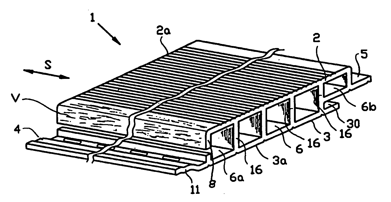
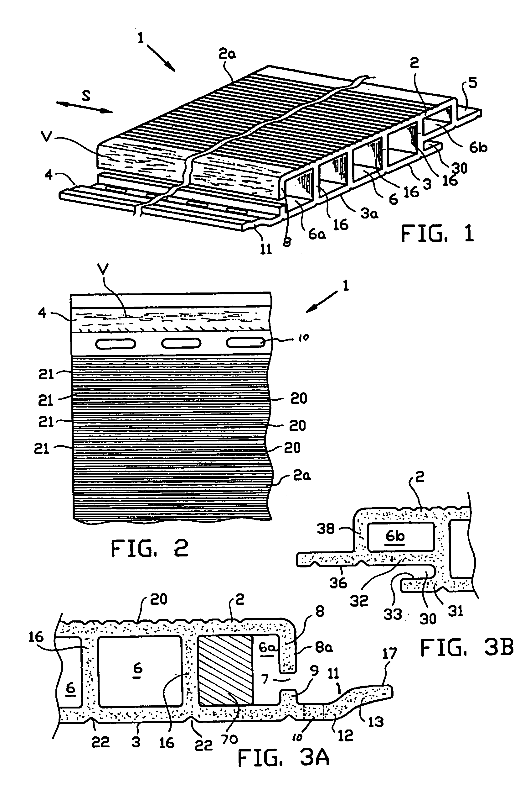
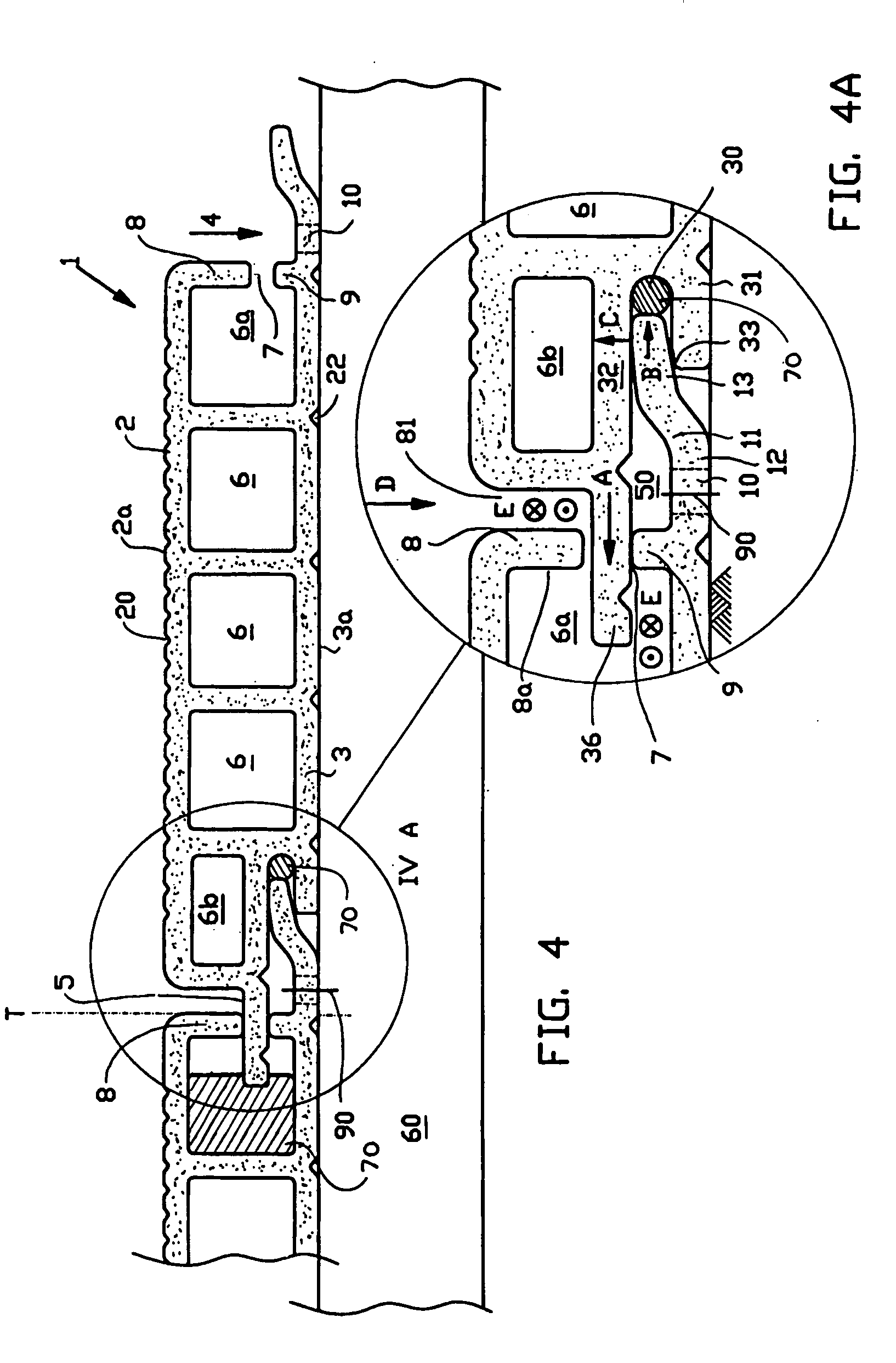
[0050] The profile part or profile member 1 is shown in FIG. 1 and further, is manufactured by an extrusion or pushtrusion process in direction S, and is formed from a composite material, comprising a matrix of synthetic thermoplastic polymer, particularly a polyolefin, preferably polypropylene, including a plurality of, for instance 70% by weight or more, preferably 70 to 80% by weight of a mixture of short wood fibres and long wood fibres, wherein the short wood fibres have a length in the range of 0.2-2 mm and the long fibres are in the range of 2-8 mm, preferably 4-6 mm. In a manner as for instance described in U.S. Pat. No. 6,929,841, the long fibres V during manufacturing have been oriented substantially in direction S, whereas the short fibres are randomly oriented. During production of the profile part 1, use is made of dried wood fibre material that contains moisture content less than 1%, preferably less than 0.5% by weight.

[0051] In the embodiment of a hollow profile, the...


PUM

PropertyMeasurementUnit
Lengthaaaaaaaaaa
Lengthaaaaaaaaaa
Percent by massaaaaaaaaaa

Abstract

A cover profile system for forming a walking surface, roof surface, wall, wall surface or retaining wall, which is formed from a plurality of generally flat, elongated hollow profile bodies, each comprising a first wall, a second wall, a first longitudinal edge and a second longitudinal edge, wherein the first longitudinal edge is provided with a first longitudinal strip having holes for attachment, wherein one of either longitudinal edges is provided with a second longitudinal strip, which at the side of the first strip that faces the first wall, extends over the first strip to at least the opposite longitudinal edge. Resilient members are provided between adjacent profile panels to avoid incorrect installation by installers and to enable traverse expansion to avoid damage or buckling of the product.

Description

CROSS-REFERENCE TO RELATED APPLICATION [0001] This application claims the benefit of Netherlands patent application NL 1022956 filed Mar. 18, 2003, and U.S. provisional application 60 / 459,815, filed Apr. 2, 2003, and is a continuation in part of U.S. patent application Ser. No. 10 / 801,491, filed Mar. 16, 2004, all of which are relied on and incorporated herein by reference.INTRODUCTION AND BACKGROUND [0002] The invention relates to an improved cover or cladding profile or section system for forming a variety of structures such as decking, roof and floor surfaces or siding, walls, a wall surface or a retaining wall. More particularly, the present invention relates to an improvement whereby a resilient member is placed at selected locations in the profile to avoid incorrect installation of the profiles and to enable traverse; i.e., side to side, expansion caused by initial moisture uptake of wood fibres. [0003] Known cover profile systems comprise elongated elements, at first only in ...

Claims


Application Information

Patent Timeline
IPC IPC(8): E04H12/00E04F13/18E04F15/10
CPCE04F13/18E04F15/10E04F2201/025E04F2203/04
Inventor VAN DIJK, DIRK
Owner TECH WOOD INT
Why Eureka
Try Eureka