Cabin for a work vehicle

a work vehicle and cabin technology, applied in the field of work vehicles, can solve the problems of reducing working efficiency and narrowing of the upper forward field of view, and achieve the effects of reducing the narrowing of the overhead space, reducing the narrowing of improving the upper forward field of view

Active Publication Date: 2007-03-01
KUBOTA LTD
View PDF7 Cites 50 Cited by
  • Summary
  • Abstract
  • Description
  • Claims
  • Application Information

AI Technical Summary

Benefits of technology

[0006] Since the air-conditioning unit is disposed rearwardly with respect to the rear end of the seat portion of the driver's seat, a low ceiling portion for accommodating the air-conditioning unit need not be formed in a front portion of the roof of the cabin. A windshield position can be set high. As a result, an improved upper forward field of view is provided.
[0007] Moreover, since the position of the air-conditioning unit is set rearwardly of the rear end of the seat portion of the driver's seat, a low ceiling portion formed in the rear of the roof in order to accommodate the air-conditioning unit would not diminish the forward field of view of the driver seated on the driver's seat, but can alleviate a narrowing of overhead space.

Problems solved by technology

This leads to narrowing of an upper forward field of view.
Then, when performing a front loader operation, the driver seated on the driver's seat has difficulty in ascertaining a position of the bucket near an upper position, resulting in a possibility of lowering working efficiency.

Method used


Image

  • Cabin for a work vehicle
  • Cabin for a work vehicle
  • Cabin for a work vehicle

Examples


first embodiment

[First Embodiment]

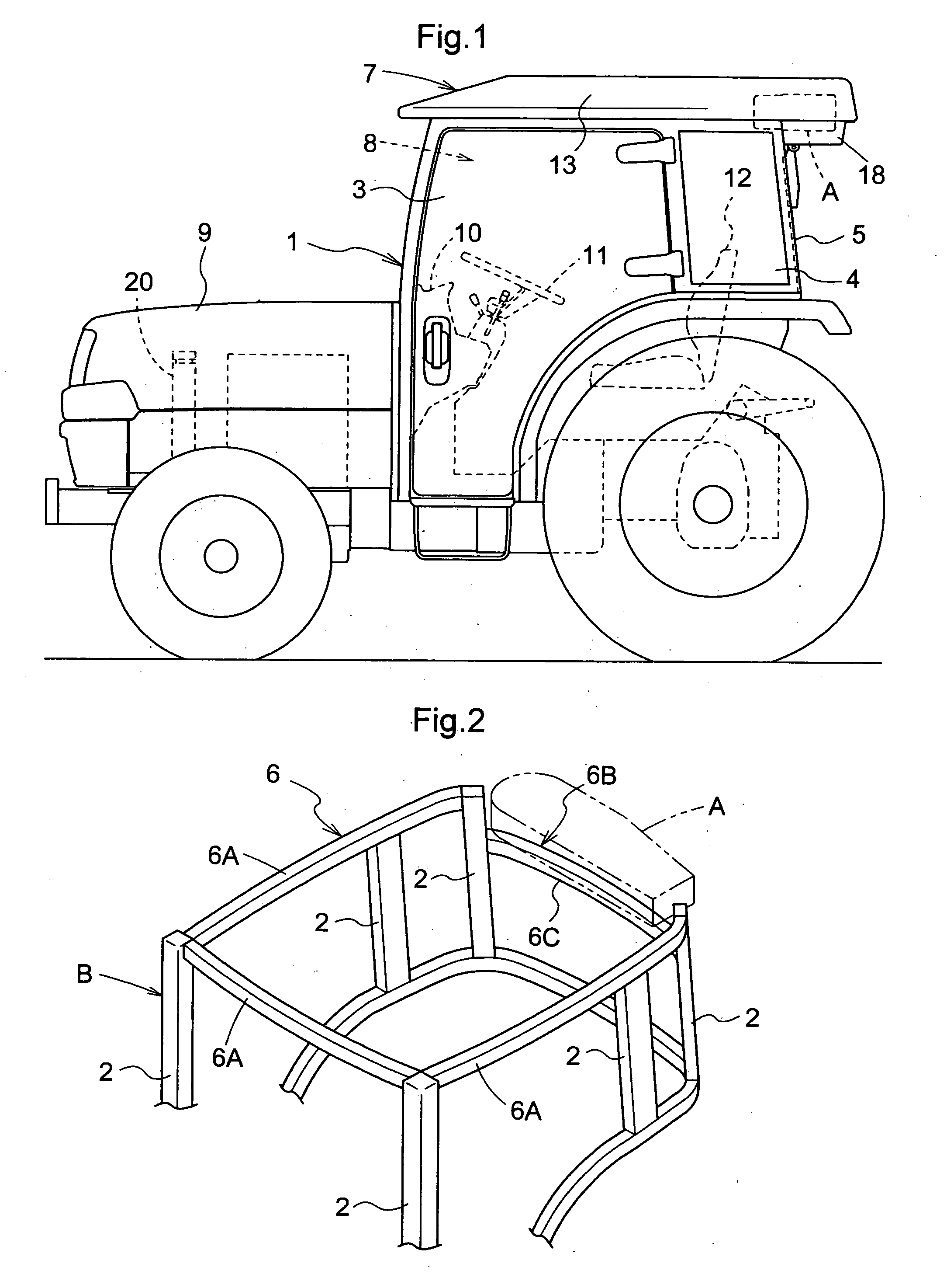
[0031] Different forms of attaching the air-conditioning unit A will be described hereinafter. A first embodiment will be described first, in which, as shown in FIGS. 2 and 3, the air-conditioning unit A is mounted above a rear end of the annular upper frame 6 extending over the upper surfaces of the vertical frames 2 constituting the structural framework B. A rear frame portion 6B located in a rear position of a hood portion 7 of the annular upper frame 6 is called a transverse frame herein.

[0032] The construction of the structural framework B for supporting the air-conditioning unit A will be described. As shown in FIG. 2, right and left vertical frames 2 are erected at connecting bend portions between fore and aft frame portions 6A and rear frame portion 6B acting as the transverse frame of the annular upper frame 6, to serve also as window frames of the rear side windows 4. A support frame 6C is laid to extend between the two vertical frames 2 and at a height ...

second embodiment

[Second Embodiment]

[0052] Next, a second embodiment will be described, in which, as shown in FIG. 6, the air-conditioning unit A is mounted forwardly of the rear end of the annular upper frame 6.

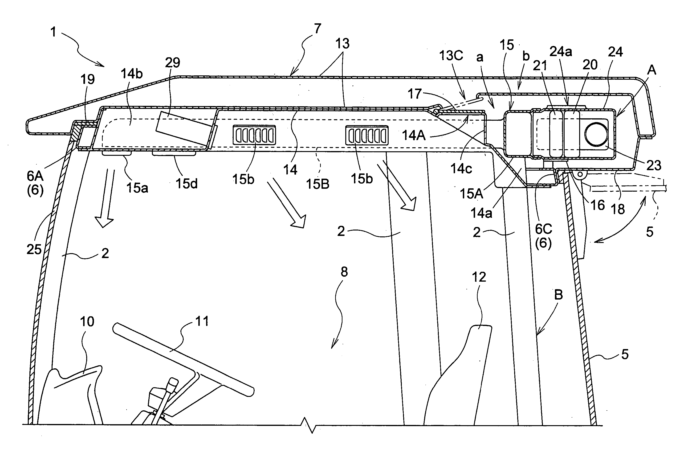
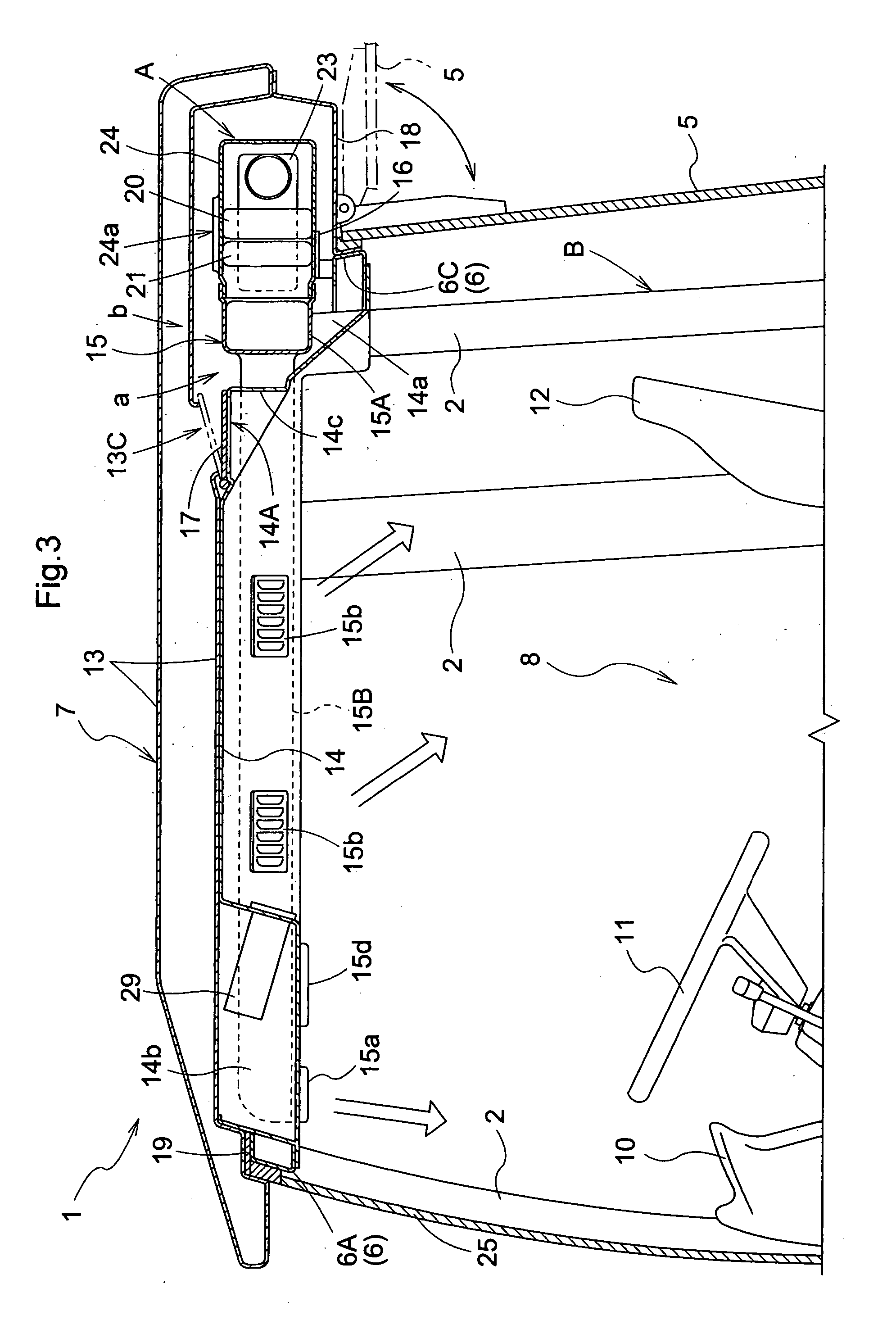
[0053] As shown in FIGS. 6 and 7, an outer roof 13 and an inner roof 14 are arranged to surround the air-conditioning unit A. An ambient air feed opening 13C is formed in the outer roof 13 forwardly of the air-conditioning unit A, and an ambient air intake opening 13B is formed in a downward surface of an eaves portion 13A of the outer roof 13 projecting rearwardly for feeding ambient air to the ambient air feed opening 13C. The inner roof 14 has a circulation opening 14A opposed to the ambient air feed opening 13C for drawing in air from the interior of the cab 1. A switching valve 17 is disposed between the ambient air feed opening 13C and circulation opening 14A to act as a valve mechanism for opening and closing the ambient air feed opening 13C and circulation opening 14A. A switching m...

third embodiment

[Third Embodiment]

[0057] Next, a third embodiment will be described, in which, as shown in FIG. 8, the air-conditioning unit A is mounted below a suspending frame portion 6D formed on the rear frame portion 6B acting as the transverse frame.

[0058] The construction of the structural framework B for supporting the air-conditioning unit A will be described. As shown in FIGS. 8 and 9, right and left vertical frames 2 are erected at connecting bend portions between fore and aft frame portions 6A and rear frame portion 6B of the annular upper frame 6, to serve also as window frames of the rear side windows 4. The suspending frame portion 6D is laid to extend between the two vertical frames 2 and at a height level a step higher than the rear frame portion 6B.

[0059] The air-conditioning unit A is suspended in a state of being slipped under the lower surface of the suspending frame portion 6D and between the neighboring vertical frames 2 supporting the suspending frame portion 6D. The susp...


PUM


Abstract

A cabin for a work vehicle comprises: a driver's seat positioned within the cabin; cabin frames including at least a transverse frame located in a rear region of the cabin; a roof supported by at least some of the cabin frames; at least one air-conditioning duct located within the roof; an air conditioning unit located rearwardly with respect to a rearward end of a seat portion of the driver's seat and adjacent the transverse frame for conditioning air and for feeding air-conditioned air into the at least one air-conditioning duct.

Description

BACKGROUND OF THE INVENTION [0001] The present invention is directed to a cabin for a work vehicle, and more particularly to an air conditioning unit within the cabin roof [0002] For arranging the air-conditioning unit, the forward half of the roof is formed as a low ceiling portion bulging downward. The air-conditioning unit is arranged in a front portion of the low ceiling portion (e.g. JP Publication No. 2005-1537 (paragraph number [0016], FIG. 1 and FIG. 2). [0003] In the above construction, the roof includes a low ceiling portion that accommodates the air-conditioning unit. This leads to narrowing of an upper forward field of view. Then, when performing a front loader operation, the driver seated on the driver's seat has difficulty in ascertaining a position of the bucket near an upper position, resulting in a possibility of lowering working efficiency. SUMMARY OF THE INVENTION [0004] The object of this invention is to provide an air-conditioning structure for a cab of a workin...

Claims


Application Information

Patent Timeline
Patent Type & Authority Applications(United States)
IPC IPC(8): B60H1/32B60H1/26
CPCB60H1/00378B60H2001/00235B60H1/00021A45D34/04A45D2034/002A45D2200/056
Inventor ICHIKAWA, NOBUSHIGENAGASAWA, SHOTAINABA, DAISUKEMUKAI, HISAOMOTOKI, AYASATO, KENICHI
Owner KUBOTA LTD
Why Eureka
Try Eureka