Undervoltage lockout circuit

Inactive Publication Date: 2008-10-09
MITSUBISHI ELECTRIC CORP
View PDF7 Cites 14 Cited by
  • Summary
  • Abstract
  • Description
  • Claims
  • Application Information

AI Technical Summary

Benefits of technology

[0016]According to the present invention, because the monitor-voltage-circuit time constant for determining the increasing rate of the monitor voltage is set higher than the reference-voltage-circuit time constant for determining the increasing rate of the reference voltage, during a period until the monitor voltage

Problems solved by technology

In such a case where the supply voltage steeply increases, the following problems may occur in the above conventional undervoltage lockout circuit.
Acco

Method used


Image

  • Undervoltage lockout circuit
  • Undervoltage lockout circuit
  • Undervoltage lockout circuit

Examples


embodiment 1

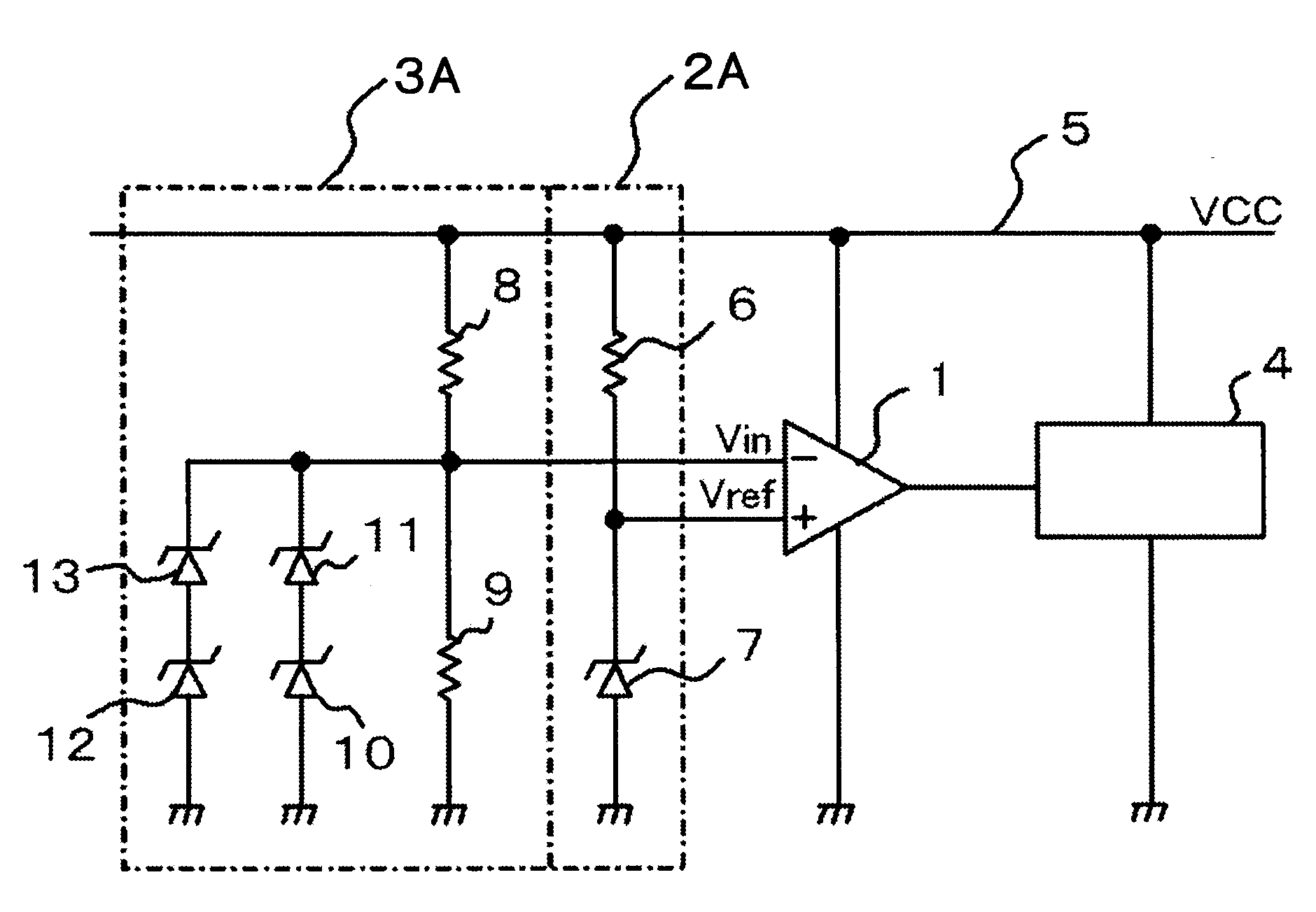
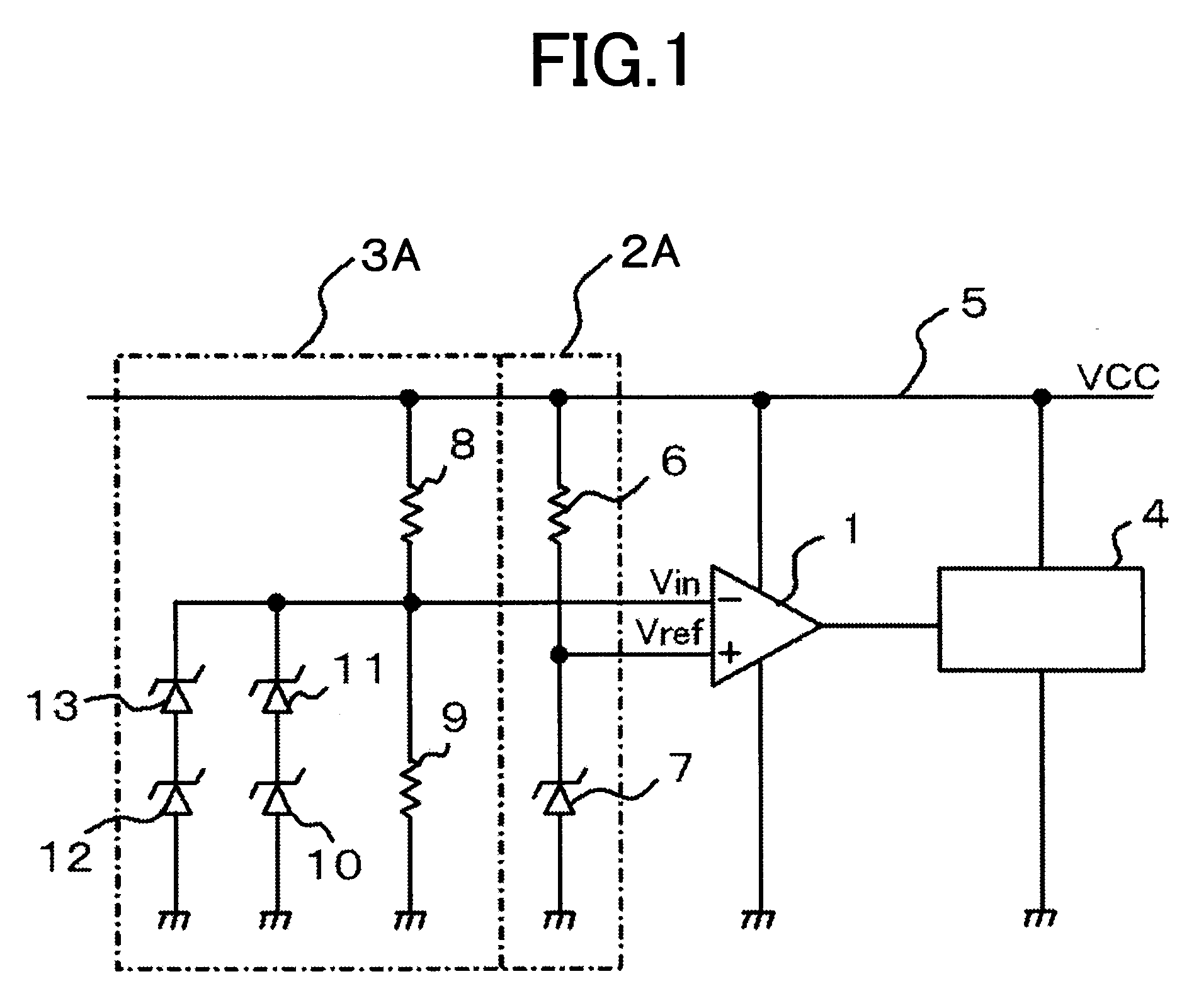
[0032]Embodiment 1 according to the present invention is explained. FIG. 1 is a circuit diagram illustrating an undervoltage lockout circuit according to Embodiment 1 of the present invention. In FIG. 1, a reference voltage (Vref) outputted from a reference-voltage circuit 2A is inputted into the non-inverting input terminal of a comparator 1. Meanwhile, a monitor voltage (Vin) outputted from a monitor-voltage circuit 3A is inputted into the inverting input terminal of the comparator 1. Thus, based on comparison results of the monitor voltage in response to the reference voltage, the L signal as the low voltage or the H signal as the high voltage is outputted from the comparator 1 to an output block circuit 4. The output block circuit 4 blocks or permits output of a gate driver, based on the H / L (high / low) signal.

[0033]The reference-voltage circuit 2A is configured with a first resistor 6 one end of which is connected to a circuit power supply 5 that supplies a supply voltage (VCC),...

embodiment 2

[0048]Embodiment 2 according to the present invention is explained. FIG. 5 is a circuit diagram illustrating an undervoltage lockout circuit according to Embodiment 2 of the present invention. In FIG. 5, the same symbols are given to members that are the same as or equivalent to those represented in FIG. 1. In FIG. 5, a reference voltage (Vref) outputted from a reference-voltage circuit 2C is inputted into the non-inverting input terminal of the comparator 1. While, a monitor voltage (Vin) outputted from a monitor-voltage circuit 3C is inputted into the inverting input terminal of the comparator 1. Thus, based on comparison results of the monitor voltage in response to the reference voltage, the L signal as the low voltage or the H signal as the high voltage is outputted from the comparator 1 to an output block circuit 4. The output block circuit 4 blocks or permits output of a gate driver based on the H / L signal.

[0049]The reference-voltage circuit 2C is configured with the first re...

embodiment 3

[0058]According to Embodiment 2, the configuration of the undervoltage lockout circuit has been represented for removing the output unblocked region 117 that occurs in a short time just after the supply voltage 15C has started to increase, in which, during the period just after the supply voltage 15C has started to increase until the reference voltage reaches the Zener breakdown voltage of the first Zener diode 7, the first N-MOS transistor 27 is made to switch off, and the second N-MOS transistor 28 is made to switch on, and in which, after the reference voltage has reached the Zener breakdown voltage of the first Zener diode 7, the first N-MOS transistor 27 is made to switch on, and the second N-MOS transistor 28 is made to switch off; however, as represented in FIG. 7, a monitor-voltage circuit 3D may be configured using a first NPN transistor 29 instead of the first N-MOS transistor 27, and a second NPN transistor 30 instead of the second N-MOS transistor 28. In this case, in th...


PUM


Abstract

An objective is to provide a highly-reliable undervoltage lockout circuit which can block and permit normal gate-driver output even when a supply voltage steeply increases. The undervoltage lockout circuit includes a reference-voltage circuit for outputting a reference voltage, a monitor-voltage circuit for outputting a monitor voltage, and a comparator for outputting, the reference voltage and the monitor voltage being inputted thereinto, a high/low signal, according to a comparison result of the reference voltage and the monitor voltage, in which the time constant of the monitor-voltage circuit for determining an increasing rate of the monitor voltage is set higher than that of the reference-voltage circuit for determining that of the reference voltage.

Description

BACKGROUND OF THE INVENTION[0001]1. Field of the Invention[0002]The present invention relates to undervoltage lockout circuits, and especially relates to an undervoltage lockout circuit for a gate driver that drives a MOSFET (metal oxide semiconductor field effect transistor) or an IGBT (insulated gate bipolar transistor).[0003]2. Description of the Related Art[0004]A gate driver that drives a MOSFET or an IGBT is generally provided with an undervoltage-lockout function (UV function) of blocking off its output when a supply voltage (VCC) decreases lower than a predetermined voltage, in order to prevent loss from increasing in the MOSFET or the IGBT.[0005]An undervoltage lockout circuit having such an undervoltage lockout function is illustrated in FIG. 12, in which a configuration equivalent to, for example, that of Japanese Laid-Open Patent Publication No. 1993-203684 (in FIG. 2) is disclosed. In FIG. 12, numeral 101 denotes a comparator. Numeral 102 denotes a Zener diode, whose ca...

Claims


Application Information

Patent Timeline
IPC IPC(8): H02H3/24
CPCH02H3/24H02H3/44
Inventor YAMAMOTO, MASAHIRO
Owner MITSUBISHI ELECTRIC CORP
Why Eureka
Try Eureka