Undervoltage lockout circuit
a technology of lockout circuit and undervoltage, which is applied in the direction of circuit arrangement, emergency protective circuit arrangement, electrical equipment, etc., can solve the problems that the gate driver cannot be normally operated and the output of the gate driver cannot be normally blocked, and achieve the effect of high-reliable undervoltage lockout circui
- Summary
- Abstract
- Description
- Claims
- Application Information
AI Technical Summary
Benefits of technology
Problems solved by technology
Method used
Image
Examples
embodiment 1
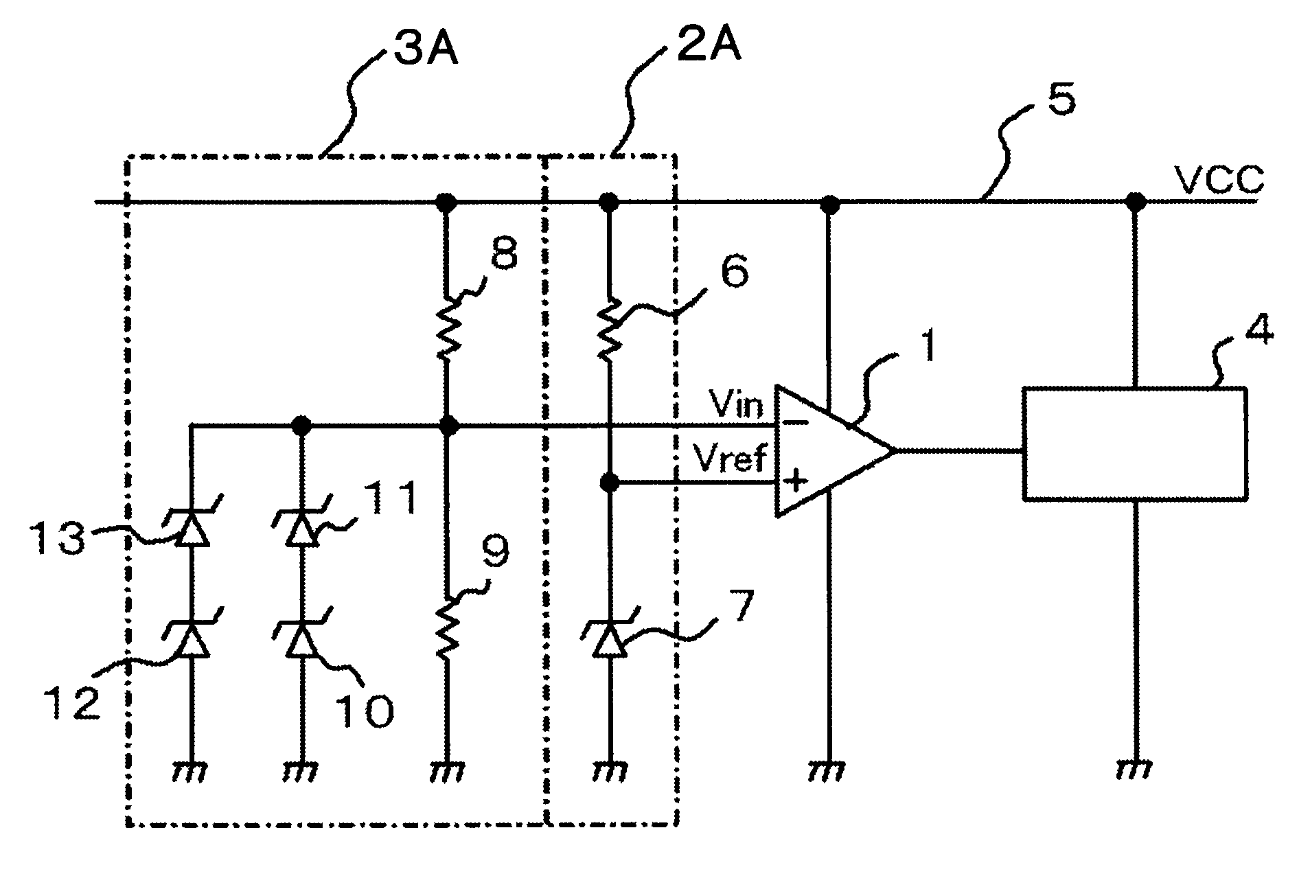
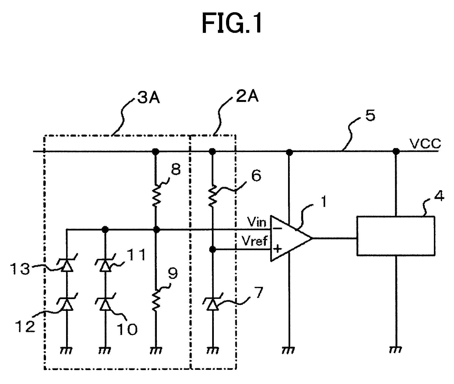
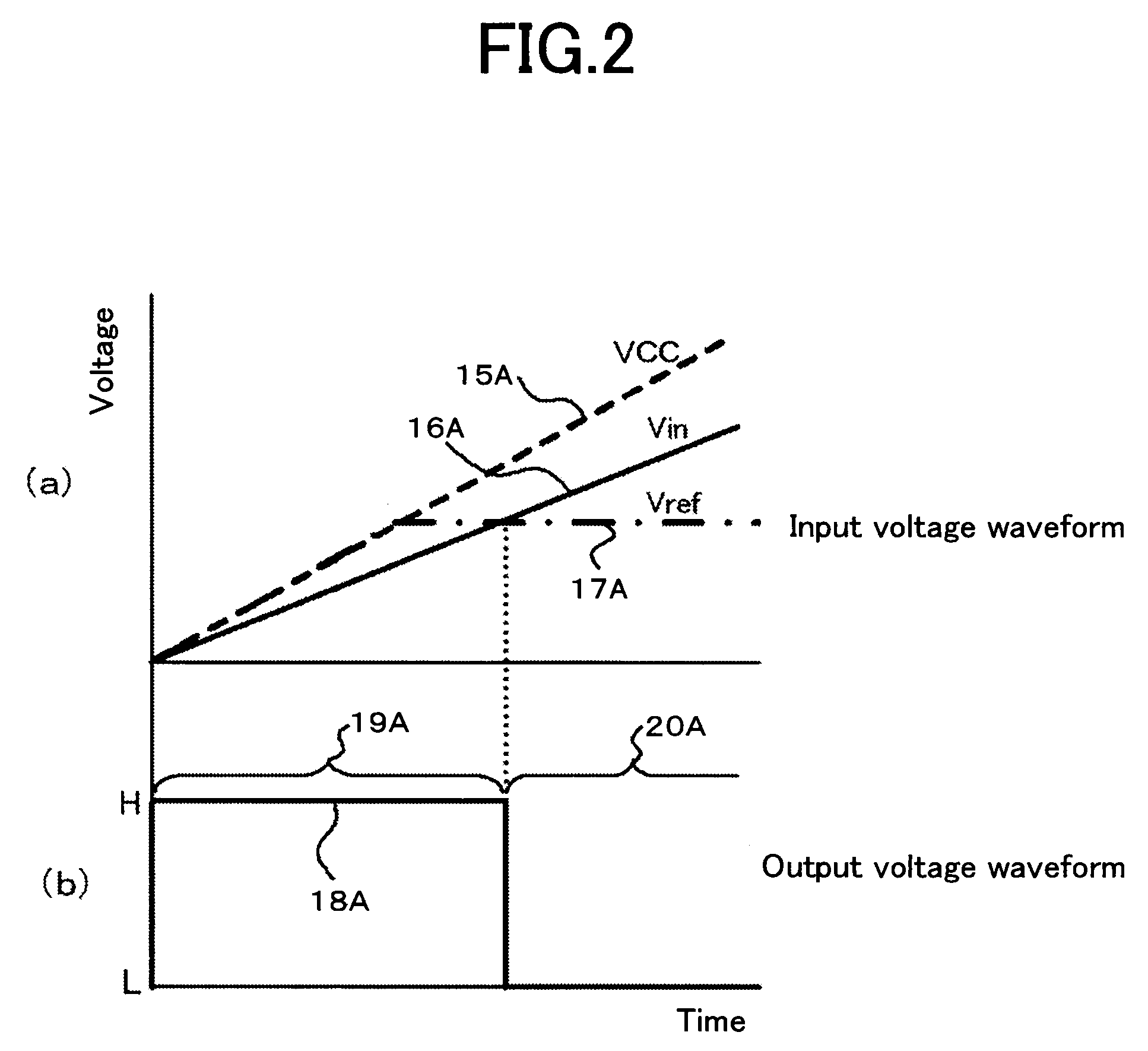
[0032]Embodiment 1 according to the present invention is explained. FIG. 1 is a circuit diagram illustrating an undervoltage lockout circuit according to Embodiment 1 of the present invention. In FIG. 1, a reference voltage (Vref) outputted from a reference-voltage circuit 2A is inputted into the non-inverting input terminal of a comparator 1. Meanwhile, a monitor voltage (Vin) outputted from a monitor-voltage circuit 3A is inputted into the inverting input terminal of the comparator 1. Thus, based on comparison results of the monitor voltage in response to the reference voltage, the L signal as the low voltage or the H signal as the high voltage is outputted from the comparator 1 to an output block circuit 4. The output block circuit 4 blocks or permits output of a gate driver, based on the H / L (high / low) signal.
[0033]The reference-voltage circuit 2A is configured with a first resistor 6 one end of which is connected to a circuit power supply 5 that supplies a supply voltage (VCC),...
embodiment 2
[0048]Embodiment 2 according to the present invention is explained. FIG. 5 is a circuit diagram illustrating an undervoltage lockout circuit according to Embodiment 2 of the present invention. In FIG. 5, the same symbols are given to members that are the same as or equivalent to those represented in FIG. 1. In FIG. 5, a reference voltage (Vref) outputted from a reference-voltage circuit 2C is inputted into the non-inverting input terminal of the comparator 1. While, a monitor voltage (Vin) outputted from a monitor-voltage circuit 3C is inputted into the inverting input terminal of the comparator 1. Thus, based on comparison results of the monitor voltage in response to the reference voltage, the L signal as the low voltage or the H signal as the high voltage is outputted from the comparator 1 to an output block circuit 4. The output block circuit 4 blocks or permits output of a gate driver based on the H / L signal.
[0049]The reference-voltage circuit 2C is configured with the first re...
embodiment 3
[0058]According to Embodiment 2, the configuration of the undervoltage lockout circuit has been represented for removing the output unblocked region 117 that occurs in a short time just after the supply voltage 15C has started to increase, in which, during the period just after the supply voltage 15C has started to increase until the reference voltage reaches the Zener breakdown voltage of the first Zener diode 7, the first N-MOS transistor 27 is made to switch off, and the second N-MOS transistor 28 is made to switch on, and in which, after the reference voltage has reached the Zener breakdown voltage of the first Zener diode 7, the first N-MOS transistor 27 is made to switch on, and the second N-MOS transistor 28 is made to switch off; however, as represented in FIG. 7, a monitor-voltage circuit 3D may be configured using a first NPN transistor 29 instead of the first N-MOS transistor 27, and a second NPN transistor 30 instead of the second N-MOS transistor 28. In this case, in th...
PUM
 Abstract
Description
Claims
Application Information
 - R&D
- Intellectual Property
- Life Sciences
- Materials
- Tech Scout
- Unparalleled Data Quality
- Higher Quality Content
- 60% Fewer Hallucinations
Browse by: Latest US Patents, China's latest patents, Technical Efficacy Thesaurus, Application Domain, Technology Topic, Popular Technical Reports.
© 2025 PatSnap. All rights reserved.Legal|Privacy policy|Modern Slavery Act Transparency Statement|Sitemap|About US| Contact US: help@patsnap.com


