
Electromagnetic impulse transmission system and method of using same

a transmission system and impulse technology, applied in the field of electromagnetic impulse transmission systems, can solve the problems of not being able to deploy the antenna, requiring a large amount of time, and may be difficult, if not impossible, for such conventional antenna deployment, and achieve the effect of convenient deploymen

Inactive Publication Date: 2007-03-01
LOCKHEED MARTIN CORP
View PDF6 Cites 8 Cited by
  • Summary
  • Abstract
  • Description
  • Claims
  • Application Information

AI Technical Summary

Benefits of technology

[0017] The present invention provides significant advantages, including: (1) providing a electromagnetic impulse transmission system having an antenna that can easily be deployed while in motion; (2) providing an electromagnetic impulse transmission system having an antenna exhibiting a low ratio of electrical reactance to electrical resistance; (3) providing an electromagnetic impulse transmission system capable of transmitting electromagnetic energy having a broad spectrum of frequencies and / or capable of transmitting low frequency electromagnetic energy; and (4) providing a electromagnetic impulse transmission system that provides an efficient electromagnetic impulse for use in sensing systems, such as impulse radar systems.

Problems solved by technology

A substantial amount of time is often required to deploy such antennas, which results in additional planning to determine the appropriate time to begin deployment so that the antenna will be available when needed.
If the antenna has not been deployed, there may not be sufficient time to deploy the antenna and transmit the electromagnetic energy in the desired time frame.
If the medium through which the vehicle is traveling has significant density, such as an atmosphere, considerable forces may act on such conventional antennas when deployed.
It may, therefore, be very difficult, if not impossible, for such conventional antennas to be deployed without damage from fast-moving vehicles.
Longer, foldable antennas require more storage space, are typically more complex, generally take longer to unfold, and are typically more susceptible to damage upon deployment.
Moreover, the use of antennas that have larger Q values in sensing systems employing short pulse, high energy sources may result in “antenna ringing”.
Antenna ringing is undesirable, as it interferes with electromagnetic energy returned from objects or targets.

Method used


Image

  • Electromagnetic impulse transmission system and method of using same
  • Electromagnetic impulse transmission system and method of using same
  • Electromagnetic impulse transmission system and method of using same

Examples


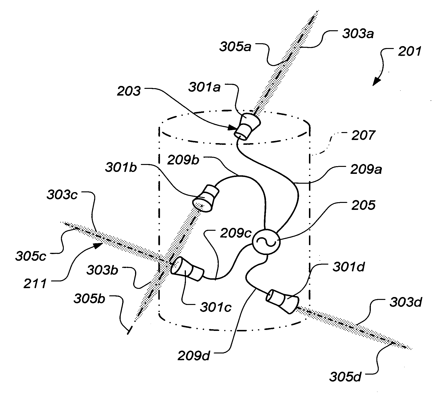
Embodiment Construction

[0035] Illustrative embodiments of the invention are described below. In the interest of clarity, not all features of an actual implementation are described in this specification. It will of course be appreciated that in the development of any such actual embodiment, numerous implementation-specific decisions must be made to achieve the developer's specific goals, such as compliance with system-related and business-related constraints, which will vary from one implementation to another. Moreover, it will be appreciated that such a development effort might be complex and time-consuming but would nevertheless be a routine undertaking for those of ordinary skill in the art having the benefit of this disclosure.

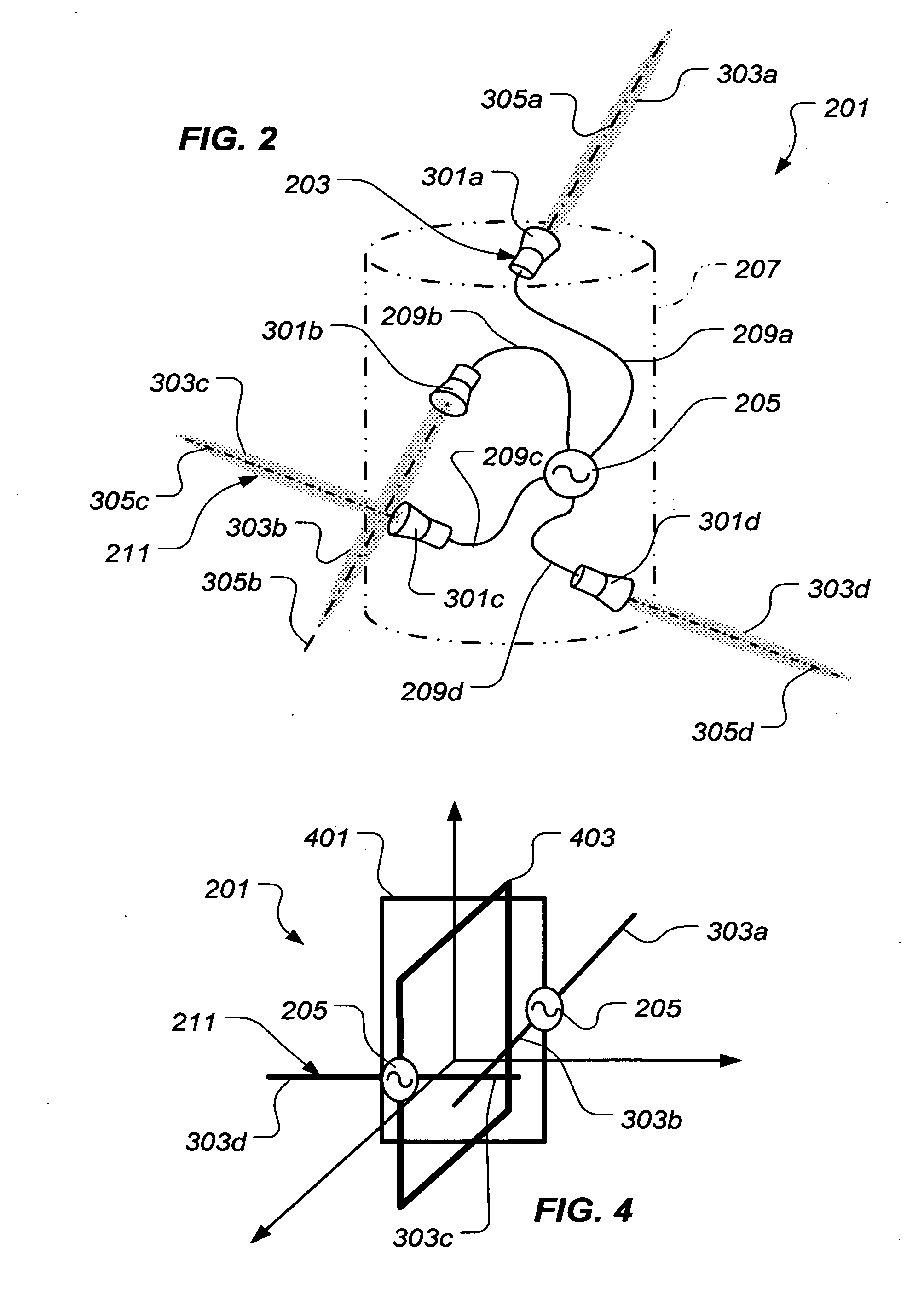
[0036] The present invention represents an electromagnetic impulse transmission system and a method of using the system. The electromagnetic impulse transmission system includes an apparatus for generating a plasma antenna, such that the electromagnetic impulse transmission syst...


PUM


Abstract

An electromagnetic impulse transmission system includes a plasma antenna generator, an electromagnetic impulse generator electrically coupled with the plasma antenna generator, and a ground plane structure operably associated with the plasma antenna generator. An electromagnetic impulse transmission system includes a plasma antenna, an electromagnetic impulse generator electrically coupled with the plasma antenna, and a ground plane operably associated with the plasma antenna. A method includes the steps of providing a plasma antenna generator, an electromagnetic impulse generator, and a ground plane structure; generating a plasma antenna with the plasma antenna generator; and transmitting an electromagnetic impulse from the electromagnetic impulse generator to the plasma antenna. The method further includes radiating the electromagnetic impulse from the plasma antenna such that at least a portion of the electromagnetic impulse is reflected by the ground plane structure.

Description

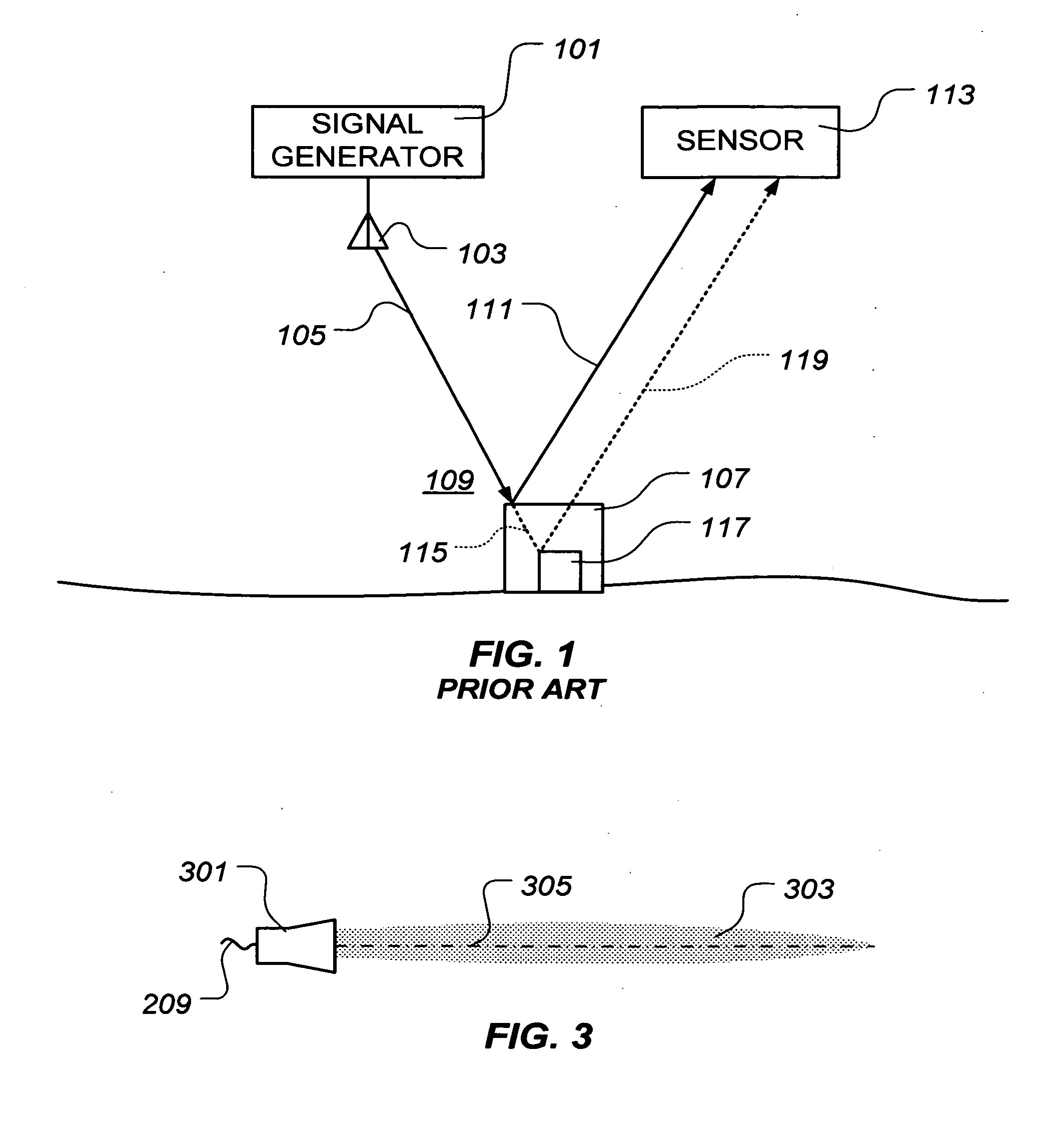
BACKGROUND [0001] 1. Field of the Invention [0002] The present invention relates to electromagnetic impulse transmission systems. In particular, the present invention relates to an electromagnetic impulse transmission system including a plasma antenna generator. [0003] 2. Description of Related Art [0004] Electromagnetic energy can be used in many ways to sense objects from a distance. Radar, for example, is reflected electromagnetic energy used to determine the velocity and location of a targeted object. It is widely used in such applications as aircraft and ship navigation, military reconnaissance, automobile speed checks, and weather observations. [0005] In certain situations, it is desirable to radiate one or more electromagnetic impulses to sense objects within the area, such as with conventional radar. Generally, as illustrated in FIG. 1, a signal generator 101 generates an electromagnetic impulse, which is radiated by an antenna 103 as an electromagnetic wave 105. Upon encoun...

Claims


Application Information

Patent Timeline
IPC IPC(8): F42C13/04
CPCG01S13/885H01Q1/366H01Q9/16H01Q21/26
Inventor WOOD, JAMES R.
Owner LOCKHEED MARTIN CORP
Learn More