Dc/dc converter

a converter and dc technology, applied in the direction of electric variable regulation, process and machine control, instruments, etc., can solve the problems of ineffective utilization of switching devices, narrow conduction angle of switching devices, increased loss of switching devices, etc., and achieves small and efficient dc/dc and high step-up/step-down ratio

Inactive Publication Date: 2007-03-01
SANKEN ELECTRIC CO LTD
View PDF11 Cites 10 Cited by
  • Summary
  • Abstract
  • Description
  • Claims
  • Application Information

AI Technical Summary

Benefits of technology

[0016] According to the present invention, it is possible to provide a small and efficient DC / DC converter having a high step-up / step-down ratio and bidirectional current.

Problems solved by technology

If the switching frequency is increased, however, loss of the switching device is increased.
When a step-up / step-down ratio of the DC power supply Vdc1 and the DC power supply Vdc2 is high, a conduction angle of the switching device becomes narrow, and the switching device cannot be utilized effectively.

Method used


Image

  • Dc/dc converter
  • Dc/dc converter
  • Dc/dc converter

Examples


first embodiment

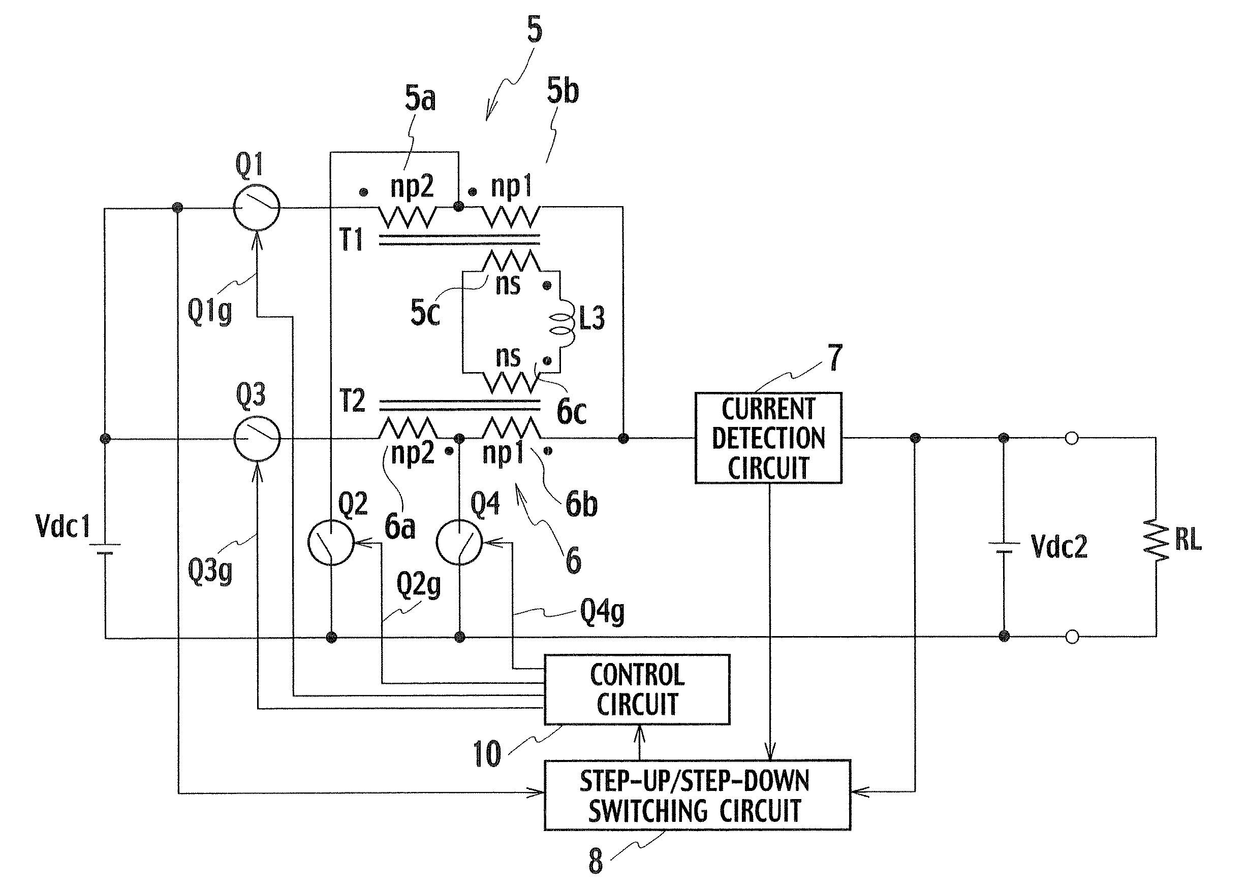
[0033]FIG. 4 is a circuit diagram of a DC / DC converter according to a first embodiment. This DC / DC converter steps up and steps down voltage of a DC power supply. The DC / DC converter includes a DC power supply Vdc1 (first DC power supply), a DC power supply Vdc2 (second DC power supply), a transformer T1 (first transformer), a transformer T2 (second transformer), a switch Q1 (first switch), a switch Q2 (second switch), a switch Q3 (third switch), a switch Q4 (fourth switch), a reactor L3, a current detection circuit 7, a step-up / step-down switching circuit 8, and a control circuit 10.

[0034] The transformer T1 includes a primary winding 5 (winding number np=np1+np2) including a first winding 5a (winding number np2) and a second winding 5b (winding number np1) being serially connected to the first winding 5a, and a secondary winding 5c (winding number ns) which is electromagnetically connected to the first winding 5a and the second winding 5b. The transformer T2 has the same configur...

second embodiment

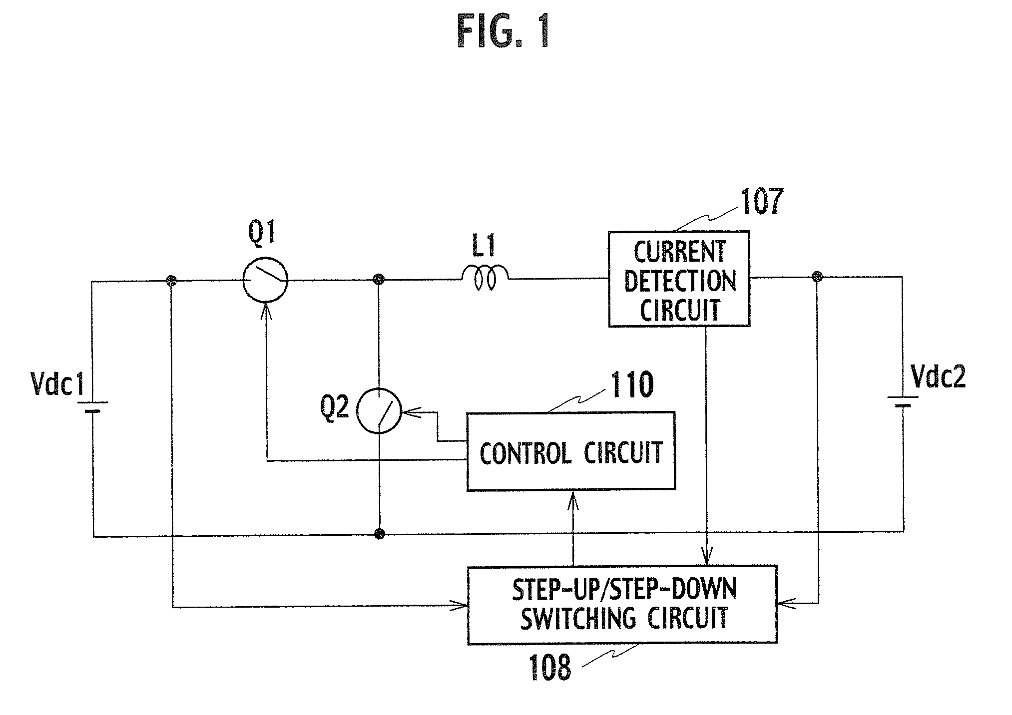
[0070]FIG. 7 is a circuit diagram of a DC / DC converter according to a second embodiment. The DC / DC converter shown in FIG. 7 is based on the DC / DC converter shown in FIG. 4, where the switch Q1 is connected between the first winding 5a and the second winding 5b of the transformer T1, and the switch Q2 is connected between the first winding 6a and the second winding 6b of the transformer T2.

[0071] The switch Q2 is connected to both ends of a series circuit to which the DC power supply Vdc1, the first winding 5a of the transformer T1, and the switch Q1 are serially connected. The switch Q4 is connected to both ends of a series circuit to which the DC power supply Vdc1, the first winding 6a of the transformer T2, and the switch Q3 are serially connected.

[0072] Since the operation of the DC / DC converter of the second embodiment having the above configuration is the same as that of the DC / DC converter shown in FIG. 4, the same effect can be obtained.

[0073] The switch Q1 and the switch...


PUM


Abstract

A DC/DC converter includes a first transformer and a second transformer each having primary windings and secondary windings respectively having first windings and second windings, a second switch connected to both ends of a first series circuit, a fourth switch connected to both ends of a second series circuit, a third series circuit being connected to both ends of the second switch and having the second winding and a second DC power supply, a fourth series circuit being connected to both ends of the fourth switch and having the second winding and the second DC power supply, a reactor connected to both ends of a series circuit having the secondary windings, and a control circuit turning ON/OFF the first and third switches with a phase difference of a half cycle and turning ON/OFF the second and fourth switches with a phase difference of a half cycle.

Description

BACKGROUND OF THE INVENTION [0001] The present invention relates to a DC / DC converter which has a high step-up / step-down ratio and operates in both directions by a regenerative operation or the like, and more particularly, to a miniaturization technique. [0002] Recently, a 42V system and a 14V system are used as electric parts of automobiles. A DC power supply (first battery) of the 42V system is charged with power provided by a power generator, charges a DC power supply (second battery) of the 14V system through the DC / DC converter, and supplies power to electric parts of the 14V system. When the second battery has excessive electric power, the power is supplied to the first battery from the second battery through the DC / DC converter. [0003] A DC / DC converter for the 14V system for driving the electric parts of the 42V system has high output current, and since the output current and current passing through a switching device are substantially the same, the switching device of high ...

Claims


Application Information

Patent Timeline
Patent Type & Authority Applications(United States)
IPC IPC(8): G05F1/12
CPCH02M3/1582H02M3/1584Y02B70/1466H02M2001/0064H02M3/1588Y02B70/10H02M1/0064
Inventor TSURUYA, MAMORU
Owner SANKEN ELECTRIC CO LTD
Why Eureka
Try Eureka