
Scanning-line interpolating circuit, scanning-line interpolating method to be used in same circuit, and image display device provided with same circuit

a scanning-line interpolation and circuit technology, applied in the direction of optical-mechanical scanning signals, instruments, television systems, etc., can solve the problems of losing half the effectiveness of interpolation in the oblique direction, flickering, bright points, dark points, etc., to reduce the “jaggies” of slanting lines, suppress display failures, and maintain the effect of smooth interpolation signals

Inactive Publication Date: 2007-03-01
PIONEER CORP +1
View PDF5 Cites 3 Cited by
  • Summary
  • Abstract
  • Description
  • Claims
  • Application Information

AI Technical Summary

Benefits of technology

[0017] In view of the above, it is an object of the present invention to provide a scanning-line interpolating circuit which is capable of reducing “jaggies” on slanting lines and of keeping smoothness of interpolating signals achieved by using slanting lines having multiple angles for interpolation and of suppressing failures in displaying caused by erroneous judgement for interpolation.

Problems solved by technology

However, the conventional scanning-line interpolating devices as described above have the following problems.
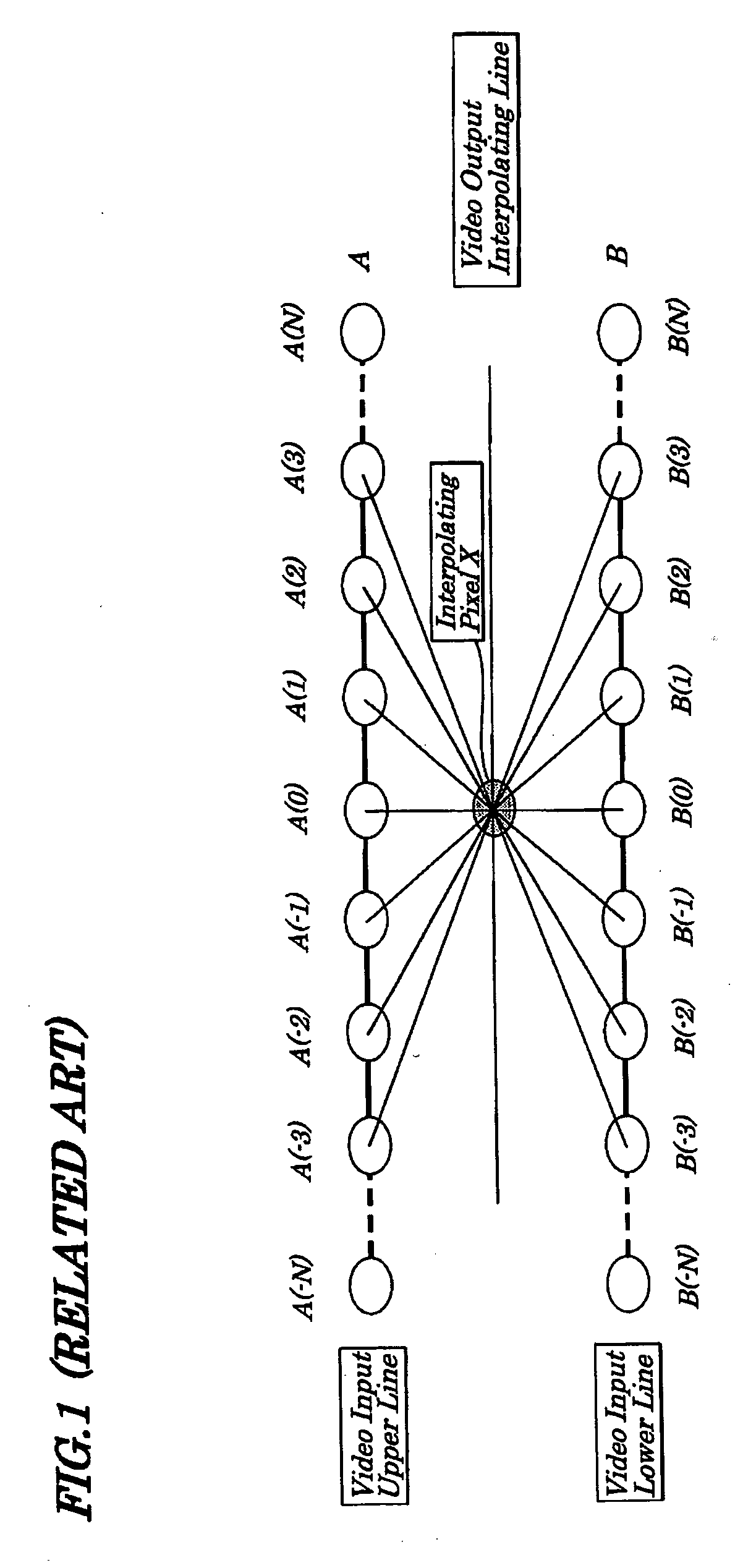
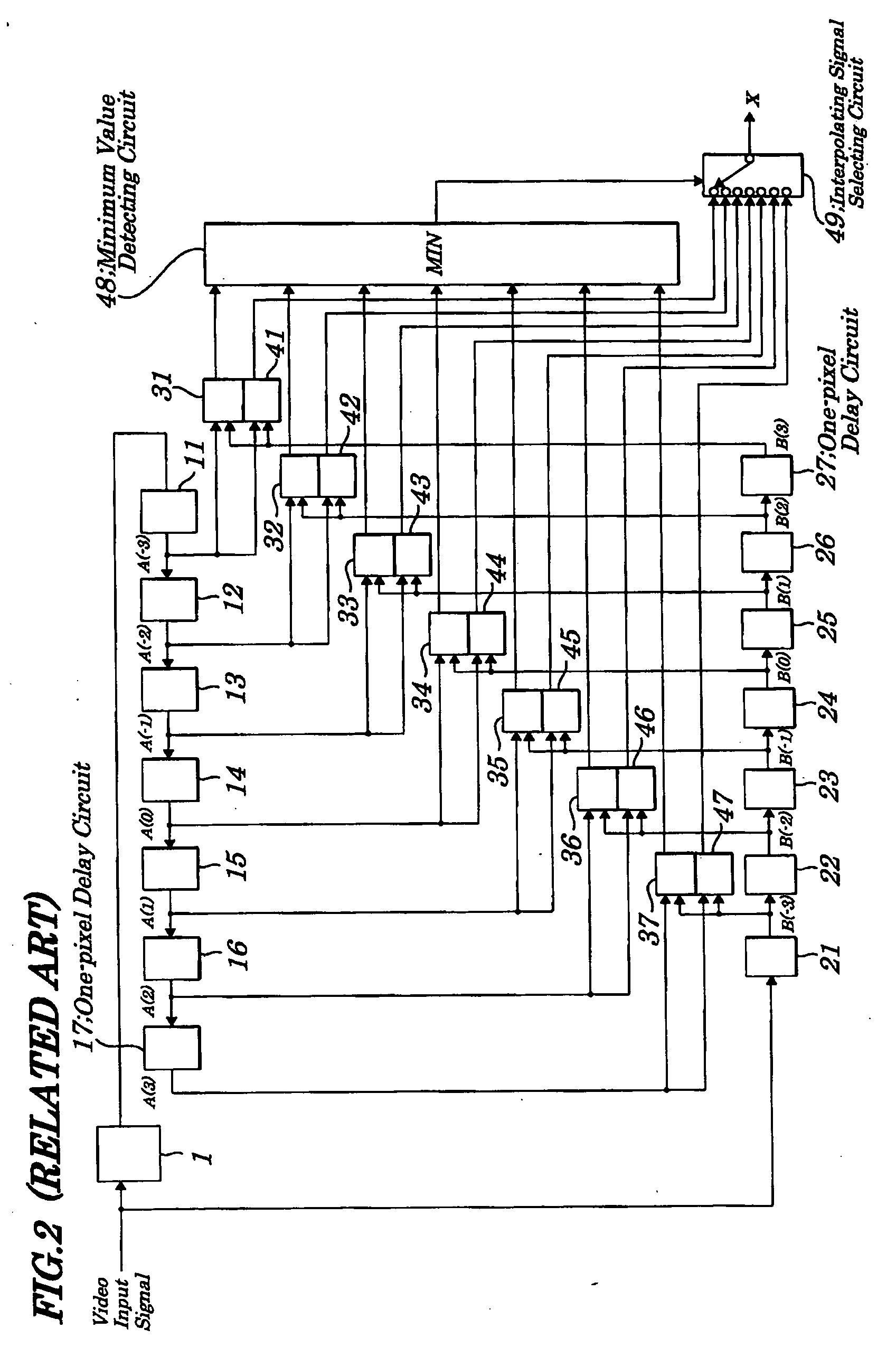
That is, in the conventional scanning-line interpolating device as shown in FIG. 2, a minimum value of an absolute value of a difference is detected by the minimum value detecting circuit 48, however, if information about an angle of an oblique line increases, in some cases, a minimum value obtained in a direction being reverse to a direction in which a minimum value is detected is employed in an actual interpolating processing and, as a result, erroneous judgement is made, which causes a flicker, bright point, dark point, or a like to occur on a display screen.
Also, the scanning-line interpolating device disclosed in the Patent Reference 2 has a problem in that, since data for interpolation in up-and-down directions and data for oblique directions are blended, one half the effectiveness of interpolation in the oblique direction is lost.
Moreover, if the data for the interpolation in up-and-down directions and data for the interpolation in the oblique direction are not blended at all, when an interpolating signal obtained by judgement for interpolation in the oblique direction and an interpolating signal obtained by judgement for interpolation in the up-and-down directions are adjacent to each other, the obtained interpolating curve is not smooth, which causes pseudo-edges to occur and a display screen to be unnatural.
The slope of the blend interpolating line becomes gentle compared with that of the slanting 15° interpolating line which shows a problem in that one half the effectiveness of the interpolation in an oblique direction is lost when compared with the case of using only the slanting 15° interpolation.

Method used


Image

  • Scanning-line interpolating circuit, scanning-line interpolating method to be used in same circuit, and image display device provided with same circuit
  • Scanning-line interpolating circuit, scanning-line interpolating method to be used in same circuit, and image display device provided with same circuit
  • Scanning-line interpolating circuit, scanning-line interpolating method to be used in same circuit, and image display device provided with same circuit

Examples


first embodiment

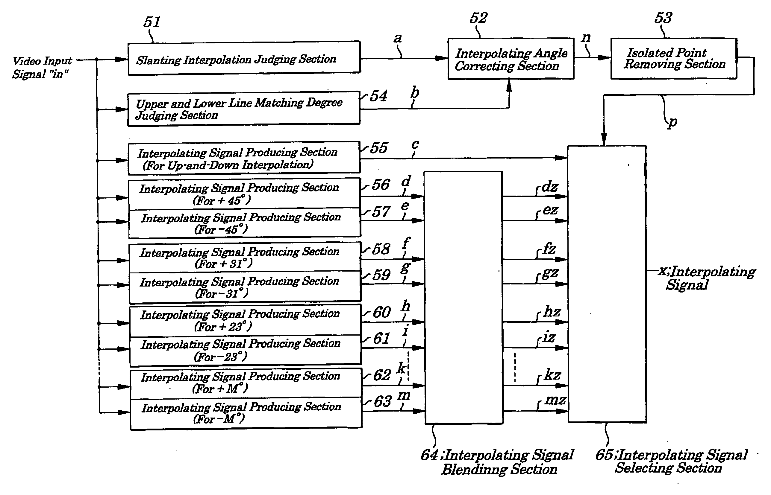
[0066]FIG. 4 is a block diagram for showing electrical configurations of main portions of a scanning-line interpolating circuit according to the first embodiment of the present invention. As shown in FIG. 4, the scanning-line interpolating circuit of the first embodiment includes a slanting interpolation judging section 51, an interpolating angle correcting section 52, an isolated point removing section 53, an upper and lower line matching degree judging section 54, an interpolating signal producing section (for up-and-down interpolation) 55, an interpolating signal producing section (for +45°) 56, an interpolating signal producing section (for −45°) 57, an interpolating signal producing section (for +31°) 58, an interpolating signal producing section (for −31°) 59, an interpolating signal producing section (for +23°) 60, an interpolating signal producing section (for −23°) 61, an interpolating signal producing sections (for other angles) (not shown), an interpolating signal produci...

second embodiment

[0101] In the scanning-line interpolating circuit of the second embodiment, the interpolating signal blending section 64 employed in the first embodiment shown in FIG. 1 is removed and the interpolating signal producing sections 56, 57, . . . , 62, and 63 are connected to the interpolating signal selecting section 65. In the second embodiment, in the isolated point removing section 53, results of judgement on interpolating angles contained in the interpolating angle judging signal “n” in synchronization with a CLOCK signal are checked and, as shown in FIG. 11 of the first embodiment, when the judgement for the slanting interpolation to be performed before and after the up-and-down direction is the interpolation at angles except ±45°, the judgement for interpolation is replaced with the interpolation at the angle of ±45° and the interpolating signal “p” is output and, therefore, while the effect of the slanting interpolation at a plurality of angles is being maintained, edges occurri...


PUM


Abstract

A scanning-line interpolating circuit is provided which is capable of reducing jaggies on slanting lines and of keeping smoothness of interpolating signals achieved by using slanting lines having multiple angles for interpolation and of suppressing failures in displaying caused by erroneous judgement. When it is judged that there is matching in pixel data between three pixels or more on an upper line and three pixels or more on a lower line, an interpolating angle judging signal is corrected to be another interpolating angle judging signal corresponding to interpolation in up-and-down directions and isolated point is removed and another interpolating angle judging signal is output. Interpolating signals are blended with other interpolating signals corresponding to interpolation in same directions and at different angles and another interpolating signals are produced. One of second interpolating signals is selected based on the interpolating angle judging signal and an interpolating signal is produced.

Description

BACKGROUND OF THE INVENTION [0001] 1. Field of the Invention [0002] The present invention relates to a scanning-line interpolating circuit, a scanning-line interpolating method and an image display device, and more particularly to the scanning-line interpolating circuit and the scanning-line interpolating method to be used for the scanning-line interpolating circuit, and an image display device provided with the scanning-line interpolating circuit, which are employed in such a case in which, in display devices including plasma display panels, liquid crystal display devices, cathode-ray tubes using a progressive scanning method, and a like, when a video input signal is converted from an interlaced scanning signal to a progressive scanning signal, a correlation is judged among pixel data on a plurality of pixels located in vertical and oblique directions and, based on the result from the judgement, interpolated pixels are generated. [0003] The present application claims priority of Ja...

Claims


Application Information

Patent Timeline
Patent Type & Authority Applications(United States)
IPC IPC(8): H04N7/01G09G5/00G09G5/18G09G5/391
CPCH04N7/012
Inventor YAMASHITA, TAKETOSHI
Owner PIONEER CORP
Learn More