Optical beam scanner, image forming device, and optical beam scanning method

Inactive Publication Date: 2007-03-01
RICOH PRINTING SYST
View PDF1 Cites 6 Cited by
  • Summary
  • Abstract
  • Description
  • Claims
  • Application Information

AI Technical Summary

Benefits of technology

[0019] According to an aspect of the present invention, it is possible to realize forming a high quality image by using optical beam scanning according to a rotary polygon mirror.

Problems solved by technology

However, even if the rotational speed of the rotary polygon mirror is switched according to the rotation reference signal, the inertia (inertial energy) of the polygon motor is still high.
It is difficult to immediately change the rotational speed in accordance with the rotation reference signal.
Accordingly, there is a problem in that a position to print in the sub scanning direction of the other rotary polygon mirrors cannot be obtained in accordance with the horizontal synchronizing signal corresponding to the reference rotary polygon mirror.

Method used


Image

  • Optical beam scanner, image forming device, and optical beam scanning method
  • Optical beam scanner, image forming device, and optical beam scanning method
  • Optical beam scanner, image forming device, and optical beam scanning method

Examples


Embodiment Construction

[0032] In the following, embodiments of the present invention in which an optical beam scanner, an image forming device, and an optical beam scanning method are preferably worked are described with reference to the accompanying drawings. It should be noted that in the embodiment below, a description is given of an example in which a color laser beam printer (hereinafter, referred to as a color printer) which comprises four image forming units is used. However, the present invention is not limited to a color printer comprising four image forming units. The color printer may comprise at least one image forming unit.

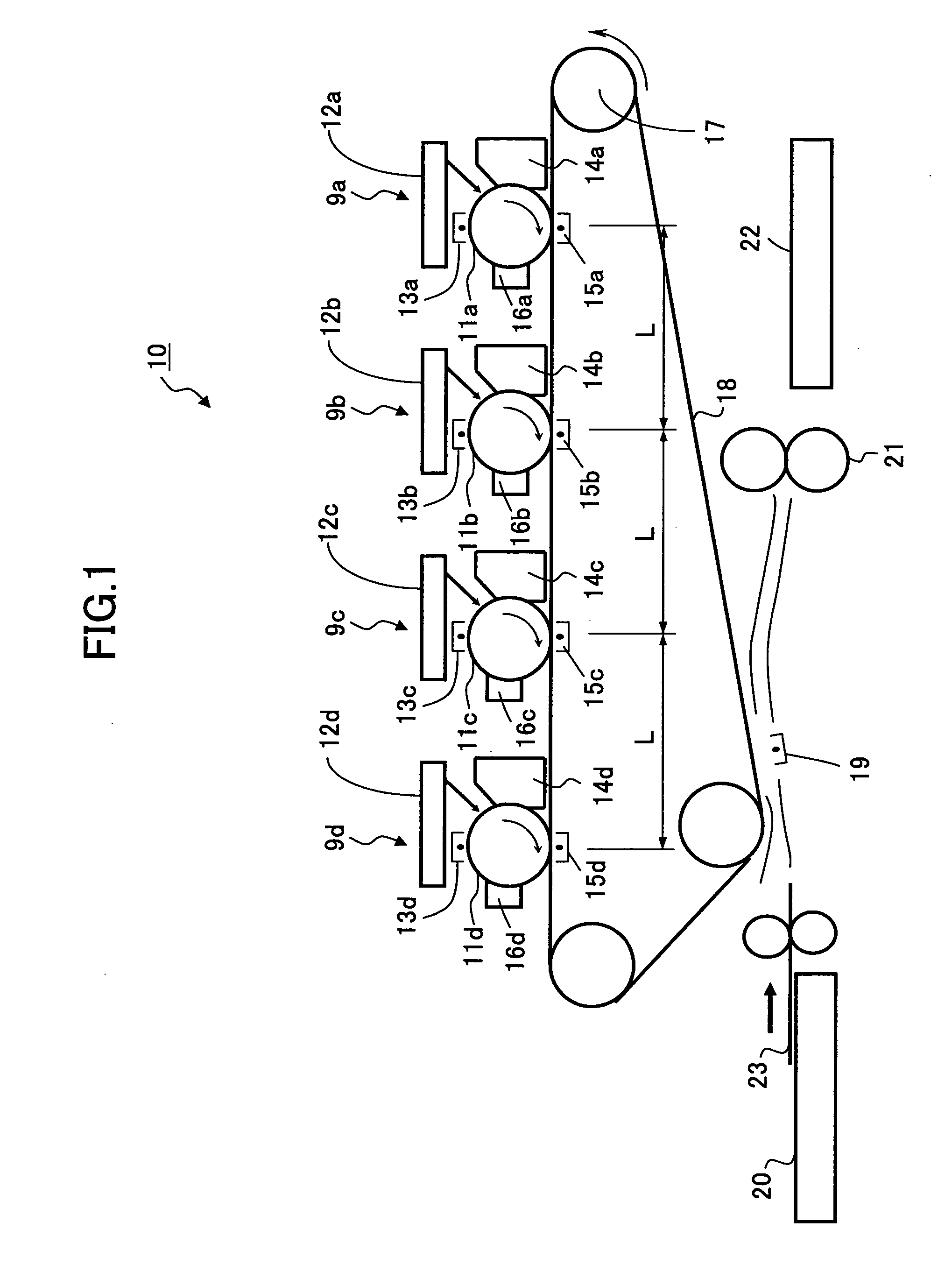
[0033]FIG. 1 is a view illustrating an example of a schematic configuration of an image forming device according to an embodiment. A color printer 10 shown in FIG. 1 as an image forming device comprises four image forming units 9a through 9d of respective colors, i.e., yellow (Y), magenta (M), cyan (C), and black (K) to form a color image by superposing monocolor images th...


PUM


Abstract

An optical beam scanner includes a driving unit rotating a rotary polygon mirror that deflects and scans an optical beam; a rotation position detection unit; a rotation control unit controlling the driving unit in accordance with a rotation reference signal and an output signal of the rotation position detection unit; an optical beam detection unit detecting the optical beam at a predetermined position on a scanning path so as to generate a horizontal synchronizing signal; a first timing generation unit generating a first reference timing so as to print a first surface; a second timing generation unit generating a second reference timing so as to print a second surface; a timing measurement unit measuring a counter value according to the horizontal synchronizing signal; and a phase control unit controlling a phase of the rotation reference signal in accordance with the counter value obtained by the timing measurement unit.

Description

BACKGROUND OF THE INVENTION [0001] 1. Field of the Invention [0002] The present invention generally relates to an optical beam scanner, an image forming device, and an optical beam scanning method, and more specifically, to an optical beam scanner, an image forming device, and an optical beam scanning method realizing forming a high quality image by using optical beam scanning according to a rotary polygon mirror. [0003] 2. Description of the Related Art [0004] Conventionally, as an optical beam scanner used in an image forming device such as a copier, a facsimile, a printer, a printing press, and the like, Japanese Laid-Open Patent Application Publication No. S64-73369 discloses an optical beam scanner which is configured to rotate plural rotary polygon mirrors which deflect and scan an optical beam onto an image supporter and detect rotating positions of the rotary polygon mirrors so that the rotary polygon mirrors are rotated at constant speed. [0005] In the above described optic...

Claims


Application Information

Patent Timeline
IPC IPC(8): G02B26/08
CPCG02B26/122G06K15/129H04N1/047H04N1/1135H04N2201/0471H04N2201/04781Y10S359/90H04N2201/04744H04N2201/04734H04N2201/04739H04N2201/02439H04N2201/04794
Inventor SHIMIZU, HITOMI
Owner RICOH PRINTING SYST
Why Eureka
Try Eureka