
Electromechanical dynamic force profile articulating mechanism

a dynamic force and articulating mechanism technology, applied in the field of mems devices, can solve the problems of deleterious and harmful to proper and/or optimal mems operation, electromechanical parameters, etc., and achieve the effects of enhancing rigidity, enhancing desired behavior, and enhancing rigidity

Inactive Publication Date: 2007-03-01
RAMBUS DELAWARE
View PDF2 Cites 49 Cited by
  • Summary
  • Abstract
  • Description
  • Claims
  • Application Information

AI Technical Summary

Benefits of technology

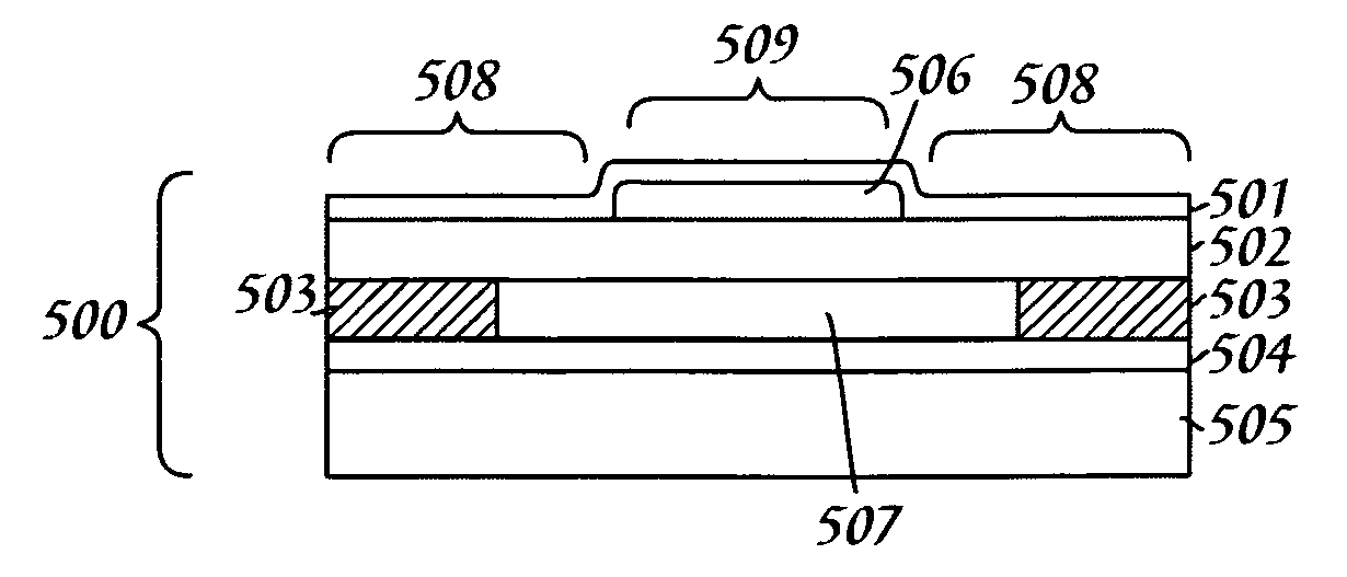
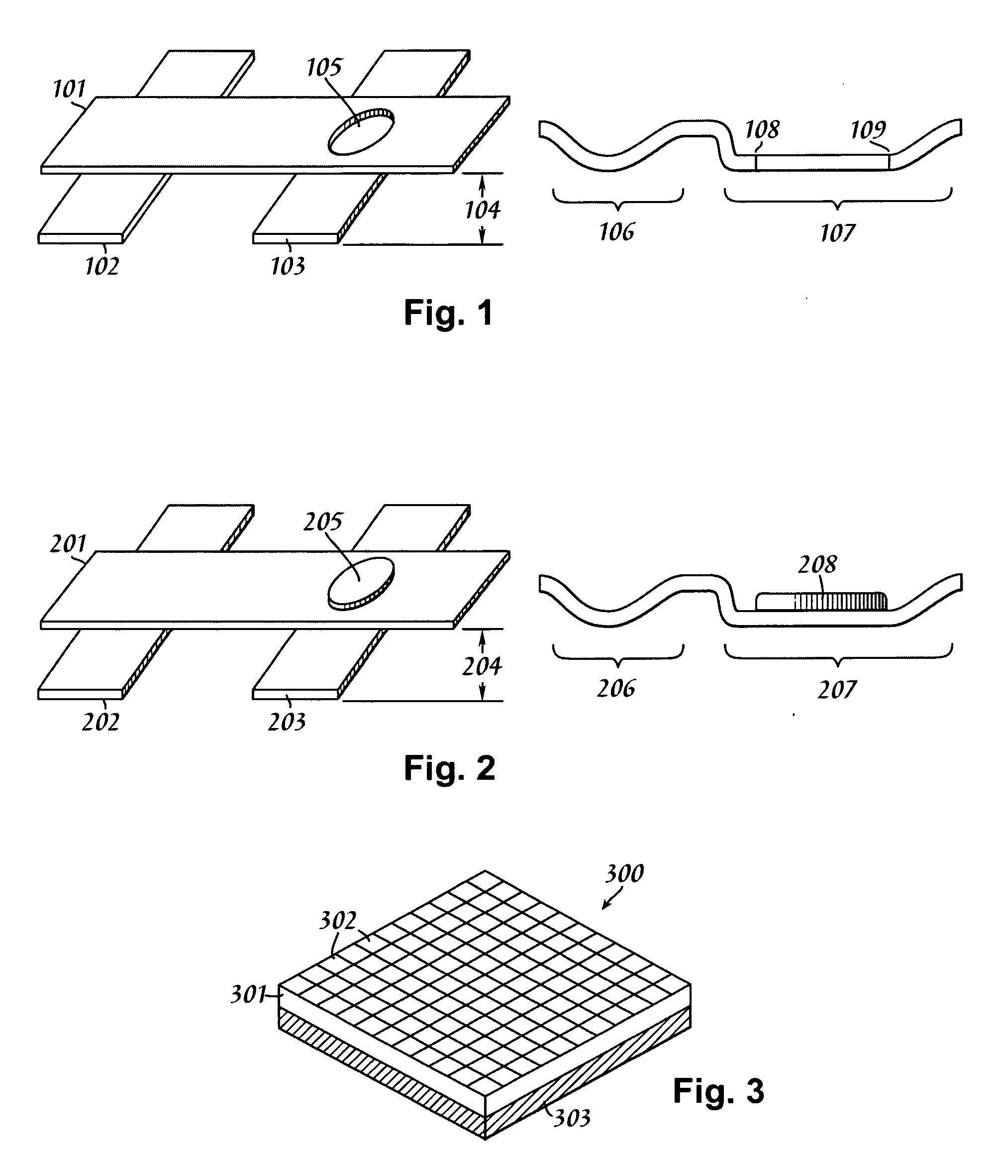
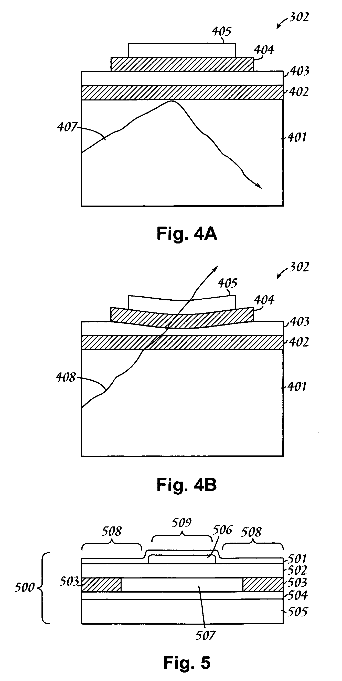
[0008] Second, geometrically articulating the shape of the conductive region on one, or the other, or both, of the conductive planes, can lead to electromechanical behaviors that can adequately emulate the desired rigid plate motion. The simplest example of this is to place a circular hole in the conductive plane, so that no electrostatic attractive forces are exerted upon the elastic membrane in the vicinity of the hole (where no conductor exists). The membrane is then deformed by forces acting at the perimeter of the circular hole and beyond. The forces at the perimeter of the circular hole will form an isodyne (a region of equal ponderomotive forces), which is the essential behavior of a rigid plate (whereby such equality of ponderomotive force is gained by keeping the respective conductive planes parallel to one another). The center of the deforming region, which would normally have a higher force due to deformational proximity and concomitant smaller gap, has no force acting upon it due to the deliberate omission of a conductor in that region. This annular isodyne region arises whether the hole in the conductive plane is situated on either, or both, of the conductive regions, but it need only be situated on one of them, thereby obviating the need for multiple precision registration of layers during fabrication of such MEMS devices.
[0009] Third, a hybridization of the first two methods can readily be configured, so that it is possible to significantly enhance the desired behavior with far less superadded material than would normally be required. In this method, fabrication sequence becomes important. The superadded material to enhance rigidity is added first, and then the conductor region is deposited on top of this structure. One gains two benefits as a consequence of this architecture: the direct benefit of rigidization due to the superadded material, and the creation of an approximated isodyne structure. The latter effect stems from the fact that, although no hole is present in the conductor, the central region of the moveable conductor is separated from the opposing fixed conductive plane by a larger distance due to the presence of the superadded material. This approximates the effect of a hole in the conductive plane, except that a small force, rather than no force, arises at the center of the architecture. The region around the superadded rigid element functions as an isodyne no less so than before, so that this hybrid architecture yields desirable electromechanical behaviors due to both explicit rigidization and isodyne configuration. The benefits of this hybrid method include reduced superaddition of rigidized material and simplicity of construction of isodynes without the need to etch or otherwise explicitly create holes in one or more of the conductive planes.

Problems solved by technology

During an elastic deformation that causes the respective plates to deviate from a mutually parallel spaced-apart relation, the electromechanical parameters for system behavior shift in significant ways that are, in most cases, regarded as deleterious and harmful to proper and / or optimal MEMS operation.

Method used


Image

  • Electromechanical dynamic force profile articulating mechanism
  • Electromechanical dynamic force profile articulating mechanism
  • Electromechanical dynamic force profile articulating mechanism

Examples


Embodiment Construction

[0019] In the following description, numerous specific details are set forth to provide a thorough understanding of the present invention. However, it will be apparent to those skilled in the art that the present invention may be practiced without such specific details. In other instances, components have been shown in generalized form in order not to obscure the present invention in unnecessary detail. For the most part, details concerning considerations of controlled selective MEMS actuation (i.e., actual operation of a rectangular n x m array of MEMS devices) and the like have been omitted inasmuch as such details are not necessary to obtain a complete understanding of the present invention and, while within the skills of persons of ordinary skill in the relevant art, are not directly relevant to the utility and value provided by the present invention.

[0020] The principles of operation to be disclosed immediately below assume the desirability of parallel plate MEMS actuator syst...


PUM


Abstract

An electromechanical dynamic force profile articulating mechanism for recovering or emulating true parallel plate capacitor actuation behaviors from deformable membranes used in MEMS systems. The curved deformation of flexible membranes causes their MEMS behavior to deviate from known interactions between rigid plates that maintain geometric parallelism during ponderomotive actuation. The present invention teaches three methods for reacquiring parallel plate behavior: superaddition or in situ integration of a rigid region within or upon the deformable MEMS membrane; creation of isodyne regions to secure parallelism by altering the force profile upon the membrane by introducing tuned and shaped voids within the conductive region associated with the membrane; and a hybrid composite approach wherein the conductive region is deposited after deposition of a raised rigid zone, thereby emulating isodyne behavior due to the increased inter-conductor distance in the vicinity of the rigid zone, in conjunction with rigidity benefits stemming directly from said zone.

Description

TECHNICAL FIELD [0001] The present invention relates in general to the field of MEMS devices, and more particularly to the field of MEMS-based flat panel displays, where the ability to control the shape and behavior of dynamically deformed membranes secures more desirable behaviors from the MEMS device in question. BACKGROUND INFORMATION [0002] MEMS-based systems, including flat panel displays that exploit the principle of frustrated total internal reflection (FTIR) to induce the emission of light from the system, may have to satisfy crucial physical criteria to function properly. The display system disclosed in U.S. Pat. No. 5,319,491, which is incorporated by reference in its entirety herein, as representative of a larger class of FTIR-based MEMS devices, illustrates the fundamental principles at play within such devices. Such a device is able to selectively frustrate the light undergoing total internal reflection within a (generally) planar waveguide. When such frustration occurs...

Claims


Application Information

Patent Timeline
Patent Type & Authority Applications(United States)
IPC IPC(8): G02B26/02
CPCG02B26/0825G02B26/02
Inventor SELBREDE, MARTIN G.KING, CAREYVAN OSTRAND, DAN
Owner RAMBUS DELAWARE
Learn More