Projector

a projector and projection image technology, applied in the field of projectors, can solve the problems of reducing brightness and contrast, unable to maintain the projection image in an appropriate manner, and following problems often occurring, and achieve the effect of facilitating the replacement of optical filters and easy release from biased states

Active Publication Date: 2007-03-01
SEIKO EPSON CORP
View PDF15 Cites 7 Cited by
  • Summary
  • Abstract
  • Description
  • Claims
  • Application Information

AI Technical Summary

Benefits of technology

[0011] An object of the invention is to provide a projector that can prevent degradation in contrast of a projection image and reduce variation in color of the projection image.

Problems solved by technology

However, when the projector with the above-described light source is diverted to home use, the wavelength band for green is intense, so that a portion to be white of the projection image becomes greenish, causing reduction in brightness and contrast when trying to correct this problem by using the optical modulators.
When the optical filter is disposed in the optical path between the light source device and the optical modulator such that the light-irradiation side surface of the optical filter is orthogonal to the optical axis of the light beam, following problems often occur.
In this condition, since unnecessary light is irradiated onto the image formation area of the optical modulator, variation in color of the projection image increases, so that the projection image cannot be maintained in an appropriate manner.

Method used


Image

  • Projector
  • Projector
  • Projector

Examples


Embodiment Construction

)

[0053] An embodiment of the invention will be described below with reference to the attached drawings.

1 Exterior Arrangement

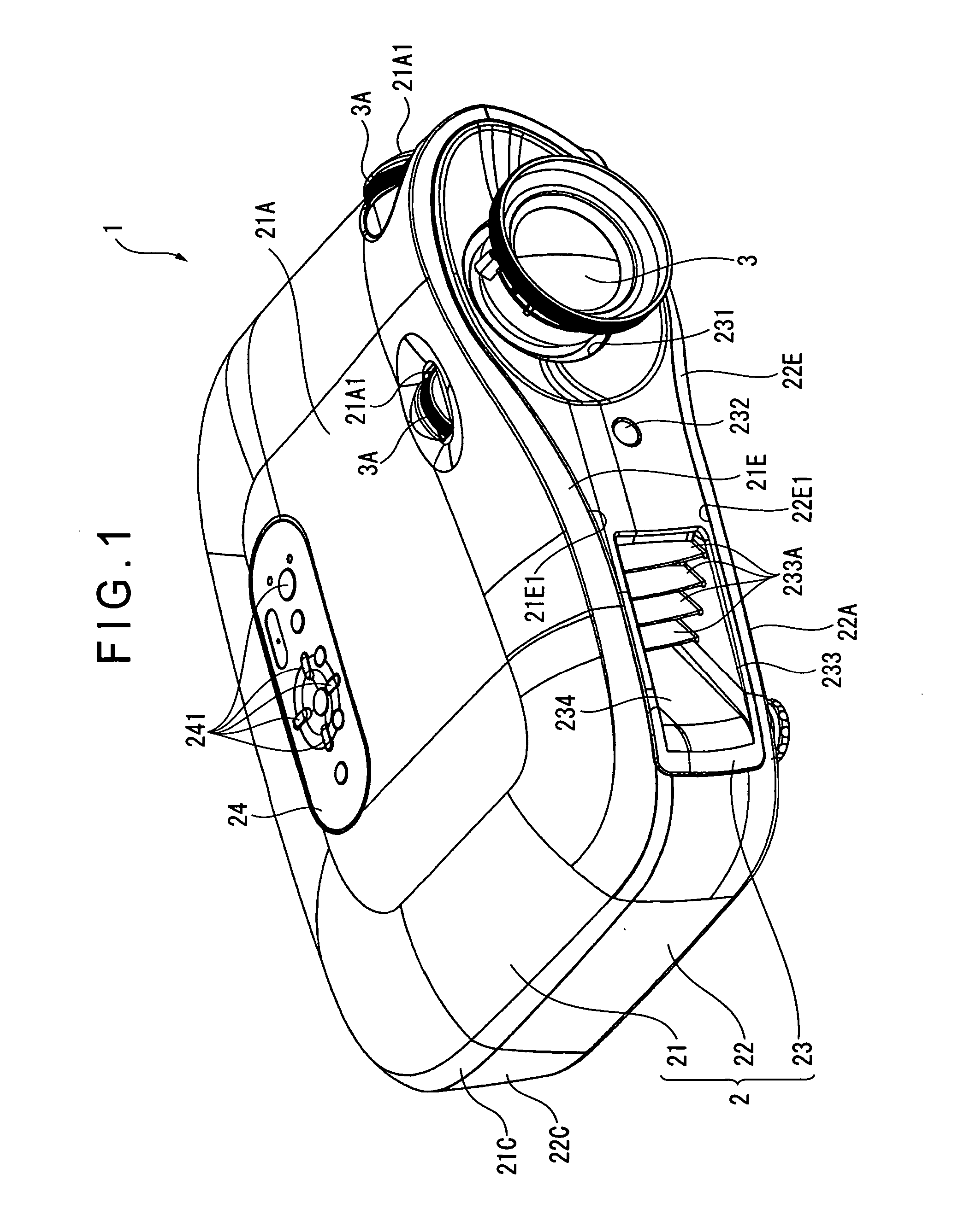
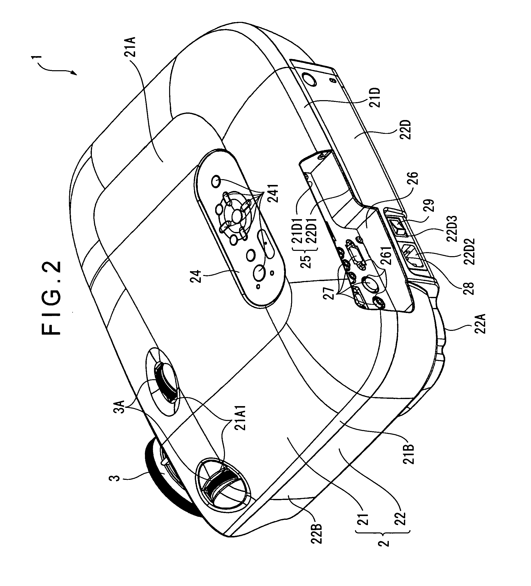
[0054]FIGS. 1 and 2 are perspective views showing exterior appearances of a projector 1. Specifically, FIG. 1 is a perspective view of the projector 1 when seen from an upper front side. FIG. 2 is a perspective view of the projector 1 when seen from an upper rear side.

[0055] The projector 1 modulates a light beam irradiated by a light source in accordance with image information to form an optical image and projects the formed optical image on a screen (not shown) in an enlarged manner. As shown in FIGS. 1 and 2, the projector 1 is provided with a substantially rectangular parallelepiped exterior case 2 and a projection lens 3 (a projection optical device) exposed from the exterior case 2.

[0056] The projection lens 3 is a lens set including a plurality of lenses housed in a cylindrical lens barrel. The projection lens 3 projects in an enlarged manner an im...


PUM


Abstract

A projector includes: a light source device, a color-separating optical system for separating a light beam irradiated by the light source device into a plurality of color light components, a plurality of optical modulators for modulating each of the separated color light components in accordance with image information, a color-combining optical device for combining optical images modulated by the plurality of optical modulators and a projection optical device for projecting the combined optical images in an enlarged manner. An optical filter that reflects a predetermined spectral component of the light beam and transmits the other spectral component is disposed in an optical path between the light source device and the optical modulators The optical filter is disposed such that a light-irradiation side surface for irradiating the light beam is inclined by a predetermined angle relative to a plane orthogonal to an optical axis of the light beam.

Description

[0001] The entire disclosure of Japanese Patent Application No. 2005-253904, filed Sep. 1, 2005, is expressly incorporated by reference herein. BACKGROUND [0002] 1. Technical Field [0003] The present invention relates to a projector. [0004] 2. Related Art [0005] Projectors have been used in the fields of presentation, home theater systems and the like. Such projectors include a projector that is provided with a light source device, a color-separating optical system for separating a light beam irradiated by the light source into a plurality of color light components, three optical modulators such as liquid crystal panels each for modulating a separated color light component in accordance with image information, a color-combining optical system such as a prism for combining the color light components modulated by the optical modulators, and a projection optical device such as a projection lens for projecting a combined optical image in an enlarged manner. [0006] When this type of proj...

Claims


Application Information

Patent Timeline
Patent Type & Authority Applications(United States)
IPC IPC(8): G02B26/00
CPCG02B27/0905G02B27/0961G02B27/1046H04N9/3182G02B27/149H04N9/3105H04N9/3141G02B27/142
Inventor NAKANO, KIYOTAKAFUJIMAKI, OSAMUHYODO, RYO
Owner SEIKO EPSON CORP
Why Eureka
Try Eureka