[0009] When the lighting device structure described in JP '766, in which the first and these second addition reflectors are provided, is employed, the light that is directly sent from the light source that would be shaded by the shade is made to be incident upon a
projection lens by the first and the second addition reflectors. Thus, incident light can be effectively used as light for irradiating forward. In this case, according to the headlamp for a vehicle described in JP '766, a
surface shape of the reflecting face of the first addition reflector is formed into an
ellipsoid of revolution, the first focus of which is at a position of the light source and the second focus of which is at a position between the first addition reflector and the second addition reflector. Therefore, a
surface shape of the second addition reflector can be set based on the assumption that a virtual light source is arranged at the second focus of the first addition reflector. Due to the foregoing, the light distribution can be easily controlled.
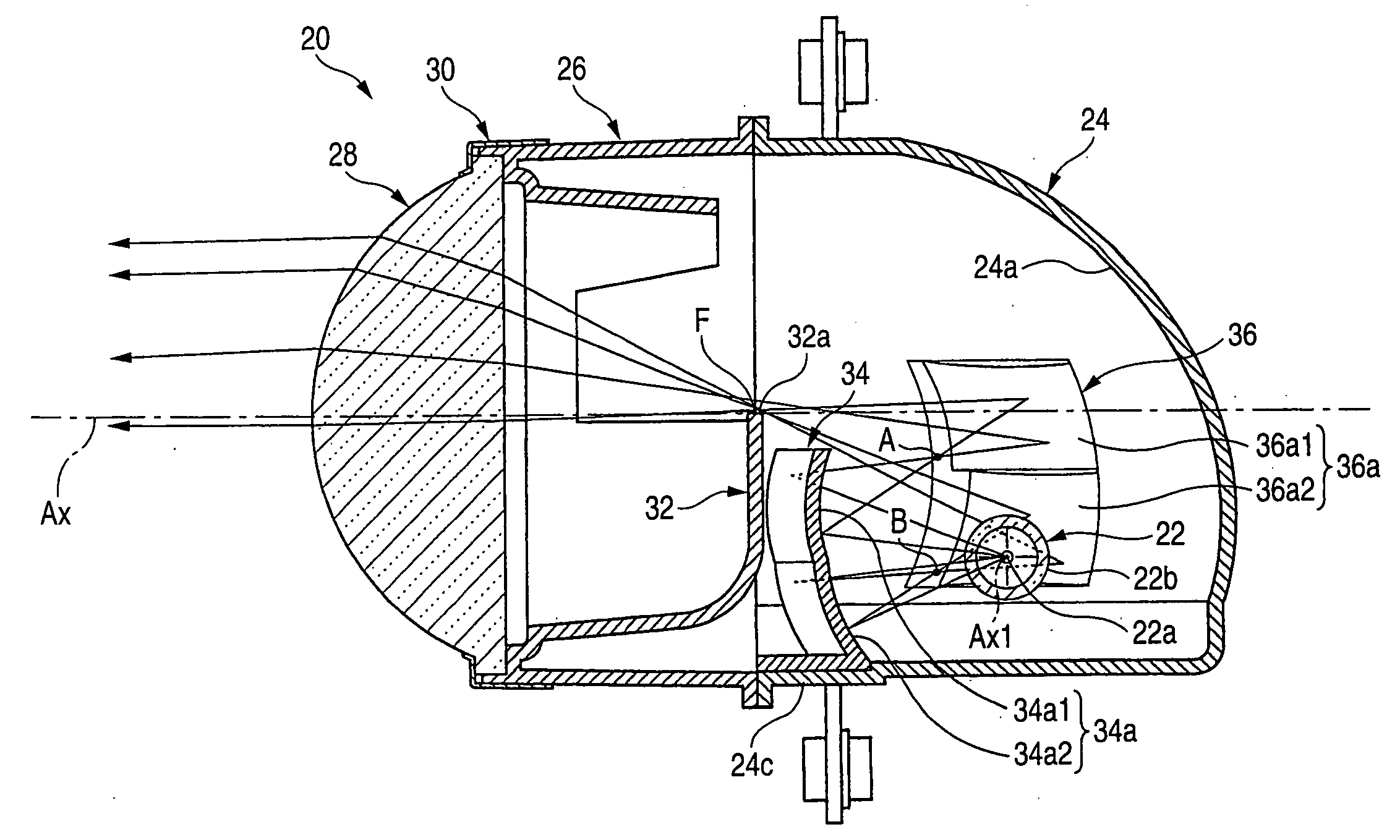
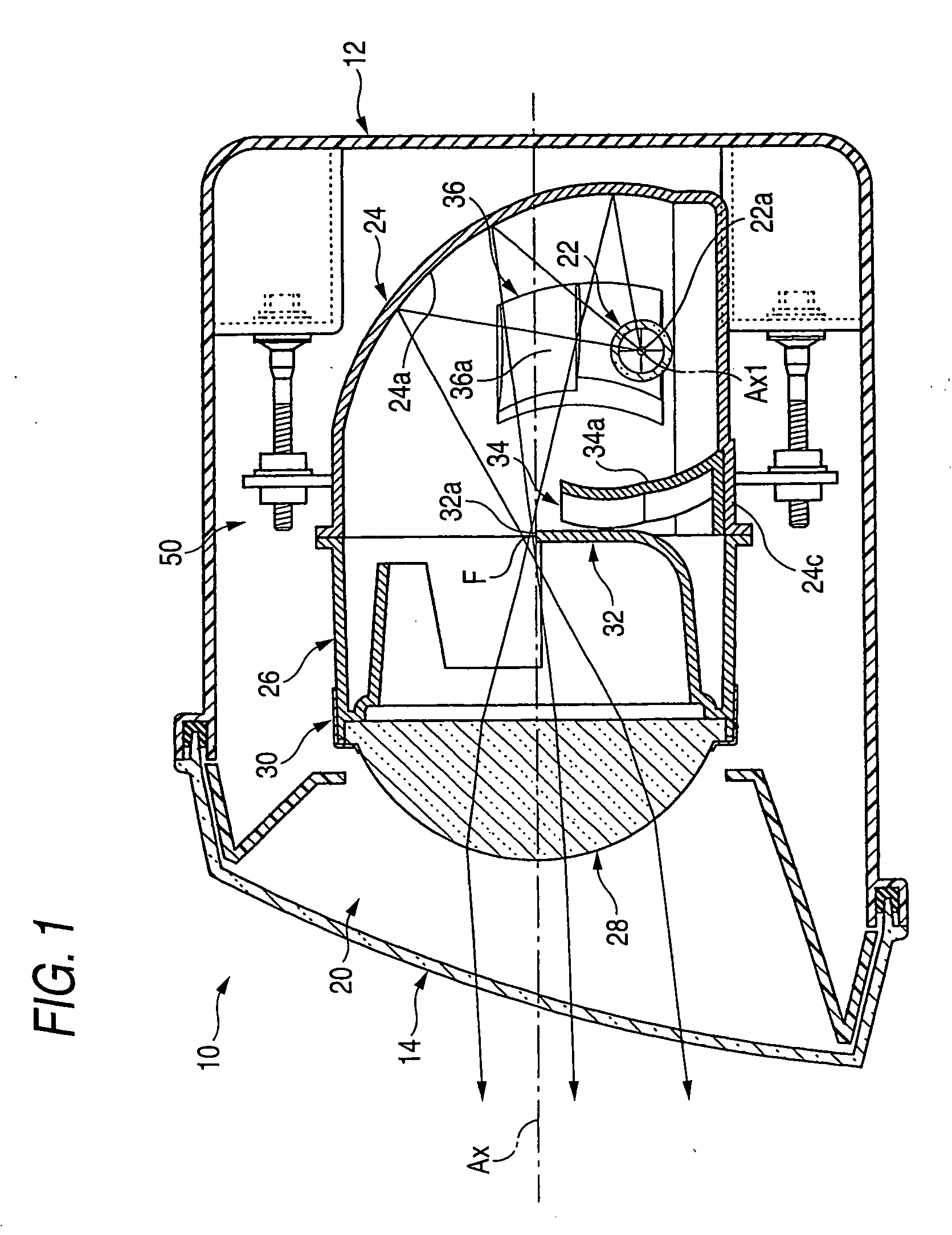
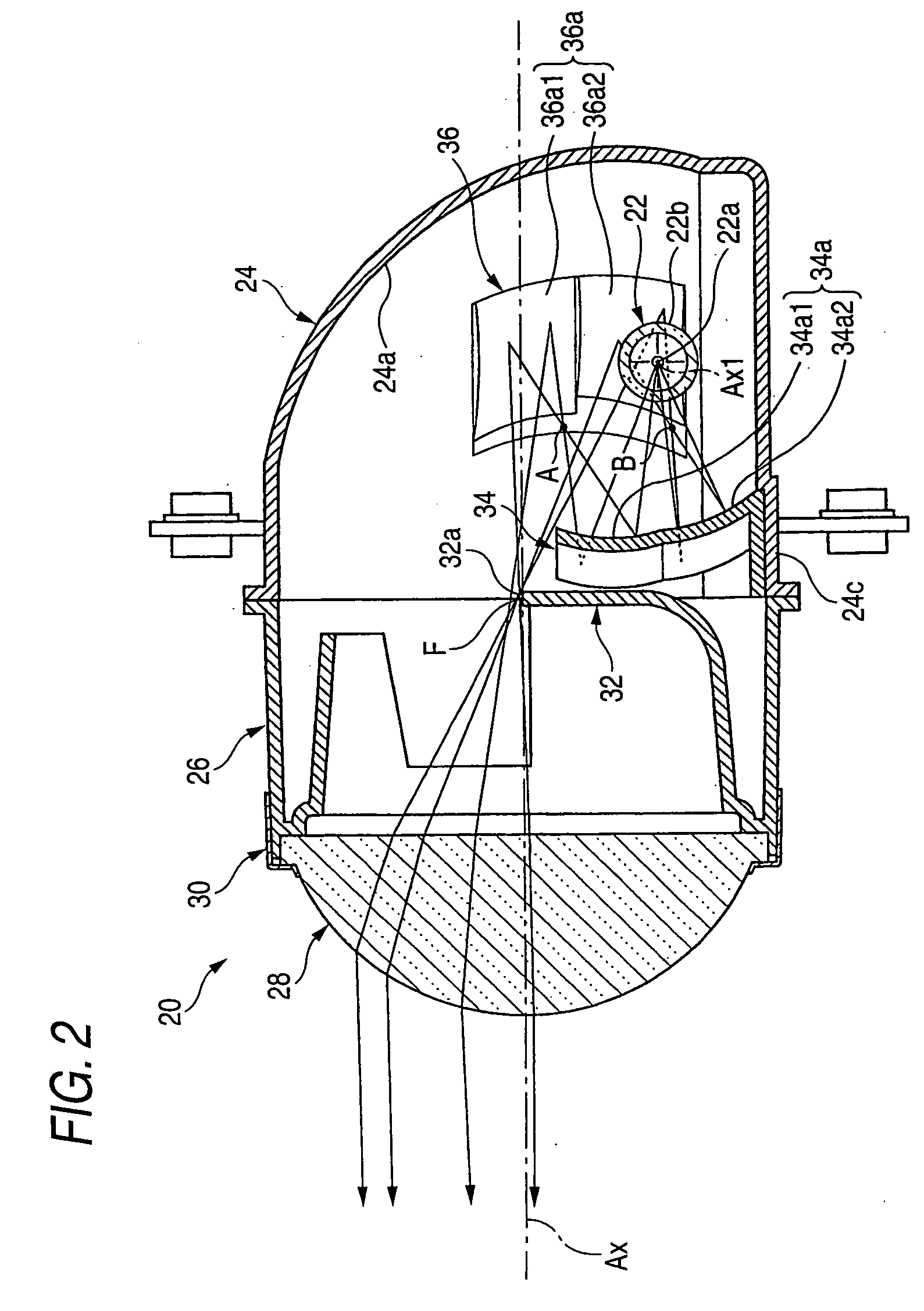
[0013] A first addition reflector for reflecting light, which is sent from the light source, toward a front region in a bulb
insertion direction on a reflecting face of the main reflector, is arranged between the light source bulb and the shade. A second addition reflector for reflecting light, which is reflected on the first addition reflector, is provided at a front region in the bulb insertion direction.
[0013] A first addition reflector for reflecting light, which is sent from the light source, toward a front region in a bulb insertion direction on a reflecting face of the main reflector, is arranged between the light source bulb and the shade. A second addition reflector for reflecting light, which is reflected on the first addition reflector, is provided at a front region in the bulb insertion direction.
[0014] A reflecting face of the first addition reflector is divided into a plurality of reflecting portions, and a
surface shape of each reflecting portion is formed as an
ellipsoid of revolution. A first focus of each of the reflecting portions is the position of the light source, and a second focus of each of the reflecting portions is at a position between the first addition reflector and the second addition reflector. The positions of the respective second focuses are different from one another. A reflecting face of the second addition reflector is divided into a plurality of reflecting portions, and the reflected light sent from the reflecting portions of the first addition reflector is incident upon the reflecting portions of the second addition reflector.
[0013] A first addition reflector for reflecting light, which is sent from the light source, toward a front region in a bulb insertion direction on a reflecting face of the main reflector, is arranged between the light source bulb and the shade. A second addition reflector for reflecting light, which is reflected on the first addition reflector, is provided at a front region in the bulb insertion direction.
[0010] However, the following problems may be encountered. When the surface shape of the reflecting face of the first addition reflector is formed into a shape of an
ellipsoid of revolution,
radiation heat emitted from the light source is concentrated upon the second focus. Accordingly, the second addition reflector located close to this second focus tends to be heated to a high temperature. Therefore, an undercoat of a vapor-deposited film forming the reflecting face of the second addition reflector is quickly deteriorated by an influence of the
radiation heat emitted from the light source.
[0005] In general, a
projector type headlamp for a vehicle is composed as follows. A projection lens is arranged on an optical axis extending in the longitudinal direction of the vehicle, and a light source is arranged at the rear of a rear side focus of the projection lens. Light emitted from this light source is reflected by a reflector and is converged toward an optical axis. In the case of a headlight for a vehicle which is used for producing a low beam, a portion of the reflected light sent from the reflector is shaded by a shade arranged so that an upper end edge of the shade is located at a position close to the rear side focus of the projection lens.
[0013] A first addition reflector for reflecting light, which is sent from the light source, toward a front region in a bulb insertion direction on a reflecting face of the main reflector, is arranged between the light source bulb and the shade. A second addition reflector for reflecting light, which is reflected on the first addition reflector, is provided at a front region in the bulb insertion direction.
[0009] When the lighting device structure described in JP '766, in which the first and these second addition reflectors are provided, is employed, the light that is directly sent from the light source that would be shaded by the shade is made to be incident upon a projection lens by the first and the second addition reflectors. Thus, incident light can be effectively used as light for irradiating forward. In this case, according to the headlamp for a vehicle described in JP '766, a surface shape of the reflecting face of the first addition reflector is formed into an ellipsoid of revolution, the first focus of which is at a position of the light source and the second focus of which is at a position between the first addition reflector and the second addition reflector. Therefore, a surface shape of the second addition reflector can be set based on the assumption that a virtual light source is arranged at the second focus of the first addition reflector. Due to the foregoing, the light distribution can be easily controlled.
[0015] The type of the above “light source bulb” is not specifically limited. For example, a
discharge bulb or
halogen lamp can be employed. The light source bulb can be inserted and fixed to the main reflector from the side of the optical axis, but the specific inserting and fixing position is not particularly limited.
[0009] When the lighting device structure described in JP '766, in which the first and these second addition reflectors are provided, is employed, the light that is directly sent from the light source that would be shaded by the shade is made to be incident upon a projection lens by the first and the second addition reflectors. Thus, incident light can be effectively used as light for irradiating forward. In this case, according to the headlamp for a vehicle described in JP '766, a surface shape of the reflecting face of the first addition reflector is formed into an ellipsoid of revolution, the first focus of which is at a position of the light source and the second focus of which is at a position between the first addition reflector and the second addition reflector. Therefore, a surface shape of the second addition reflector can be set based on the assumption that a virtual light source is arranged at the second focus of the first addition reflector. Due to the foregoing, the light distribution can be easily controlled.
[0008] When the side insertion type lighting device structure described in JP '830 is employed, it is possible to make the lighting device compact by reducing a length in the longitudinal direction of the lighting device. However, because the light source is composed as a linear light source extending in the bulb axis direction, an amount of light incident upon a front region in the bulb insertion direction on the reflecting face of the reflector is extremely small. Accordingly, it is impossible to ensure a sufficient brightness of the light
distribution pattern for a low beam. This is because the light distribution characteristics of the linear light source provide a high
luminous intensity in the direction perpendicular to the bulb axis and a low
luminous intensity in the direction of the bulb axis.
[0009] When the lighting device structure described in JP '766, in which the first and these second addition reflectors are provided, is employed, the light that is directly sent from the light source that would be shaded by the shade is made to be incident upon a projection lens by the first and the second addition reflectors. Thus, incident light can be effectively used as light for irradiating forward. In this case, according to the headlamp for a vehicle described in JP '766, a surface shape of the reflecting face of the first addition reflector is formed into an ellipsoid of revolution, the first focus of which is at a position of the light source and the second focus of which is at a position between the first addition reflector and the second addition reflector. Therefore, a surface shape of the second addition reflector can be set based on the assumption that a virtual light source is arranged at the second focus of the first addition reflector. Due to the foregoing, the light distribution can be easily controlled.
[0013] A first addition reflector for reflecting light, which is sent from the light source, toward a front region in a bulb insertion direction on a reflecting face of the main reflector, is arranged between the light source bulb and the shade. A second addition reflector for reflecting light, which is reflected on the first addition reflector, is provided at a front region in the bulb insertion direction.
[0014] A reflecting face of the first addition reflector is divided into a plurality of reflecting portions, and a surface shape of each reflecting portion is formed as an ellipsoid of revolution. A first focus of each of the reflecting portions is the position of the light source, and a second focus of each of the reflecting portions is at a position between the first addition reflector and the second addition reflector. The positions of the respective second focuses are different from one another. A reflecting face of the second addition reflector is divided into a plurality of reflecting portions, and the reflected light sent from the reflecting portions of the first addition reflector is incident upon the reflecting portions of the second addition reflector.
[0013] A first addition reflector for reflecting light, which is sent from the light source, toward a front region in a bulb insertion direction on a reflecting face of the main reflector, is arranged between the light source bulb and the shade. A second addition reflector for reflecting light, which is reflected on the first addition reflector, is provided at a front region in the bulb insertion direction.


