Optical disk shred operation with detection

a technology of optical disk and detection, applied in the direction of optical discs, recording signal processing, instruments, etc., can solve the problems of insufficient data protection, insufficient data protection, and insufficient data protection, etc., to achieve the effect of efficient and effective operation and dependent on the efficiency of such an operation

Inactive Publication Date: 2007-03-01
PLASMON LMS
View PDF16 Cites 29 Cited by
  • Summary
  • Abstract
  • Description
  • Claims
  • Application Information

AI Technical Summary

Benefits of technology

[0006] Generally speaking, the present invention provides a data shred operation to an optical storage media by overwriting the data portion of a relevant data sector with a continuous series of predetermined characters. Any addressing and synchronization information for that particular sector is left alone, thus allowing for sector location and addressing. Overwriting only the data portion of the sector allows for easy identification as a “shredded” sector, which provides several advantages. Further, optical data destruction of the present invention uses a secure two-pass shred operation. The first pass is for the destruction of the data and the second pass is to verify that the operation was successfully completed.
[0008] As mentioned above, an objective of the present invention is to insure that data stored on the storage media is no longer decipherable by subsequent operations. Consequently, the primary focus of the present invention is on the data storage areas within each data sector. As such, the data shred operation of the present invention carries out steps to overwrite the data storage area without disturbing information stored in other areas of the data sector. By destroying or shredding data in this manner, the data storage system can easily recognize the shredded sectors during subsequent operations, thus insuring proper operation in the future.
[0011] It is a further object of the present invention to provide a data shredding operation which is efficient and effective. The efficiency of such an operation is dependent upon the speed at which the operation can be carried out, along with the effectiveness. Consequently, the desired process should be very quickly carried out to destroy data so that is no longer decipherable.
[0012] It is another object of the present invention to provide a data shredding operation which will not create further confusion for the data storage system. Hence, it is necessary to destroy or shred data in such a manner so that it can subsequently be identified as shredded data. Consequently, the data storage system will be able to deal with this shredded information in a reasonable and logical manner.

Problems solved by technology

Data security and data privacy are continuing issues in the world today.
Naturally, those in the data storage industry are challenged to provide their assistance in dealing with these issues.
In the optical media storage industry, no solution presently exists to insure this data destruction is accomplished.
In the hard disk industry, the approach to data destruction is the use of multi-pass erase or overwrite operations, rewriting a specific set of patterns as many a ten times. As might be anticipated, this multi-pass overwrite operation can be very time consuming.
Further, if this technique is not used, the data (documents or files) may still be present on the disk creating a possibility that the data can be recovered, thus presenting a potential liability risk for business processes.
In addition, there is no indication that the data has been destroyed, which may create problems during subsequent operation.
This is obviously undesirable when the specific goal is to completely erase or destroy the data.
Again, this multi-pass overwrite operation can be very time consuming and is thus undesirable.

Method used


Image

  • Optical disk shred operation with detection
  • Optical disk shred operation with detection
  • Optical disk shred operation with detection

Examples


Embodiment Construction

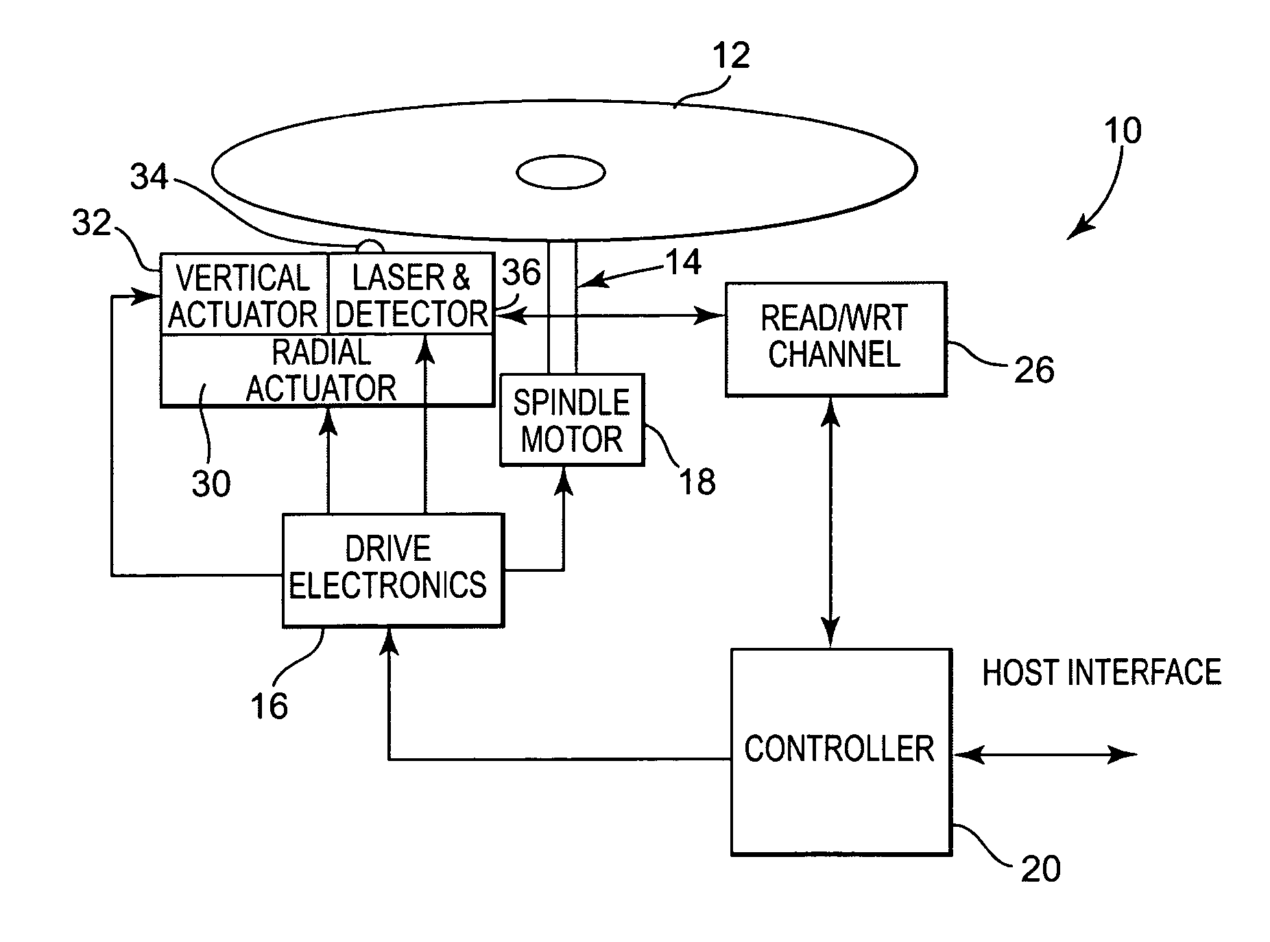
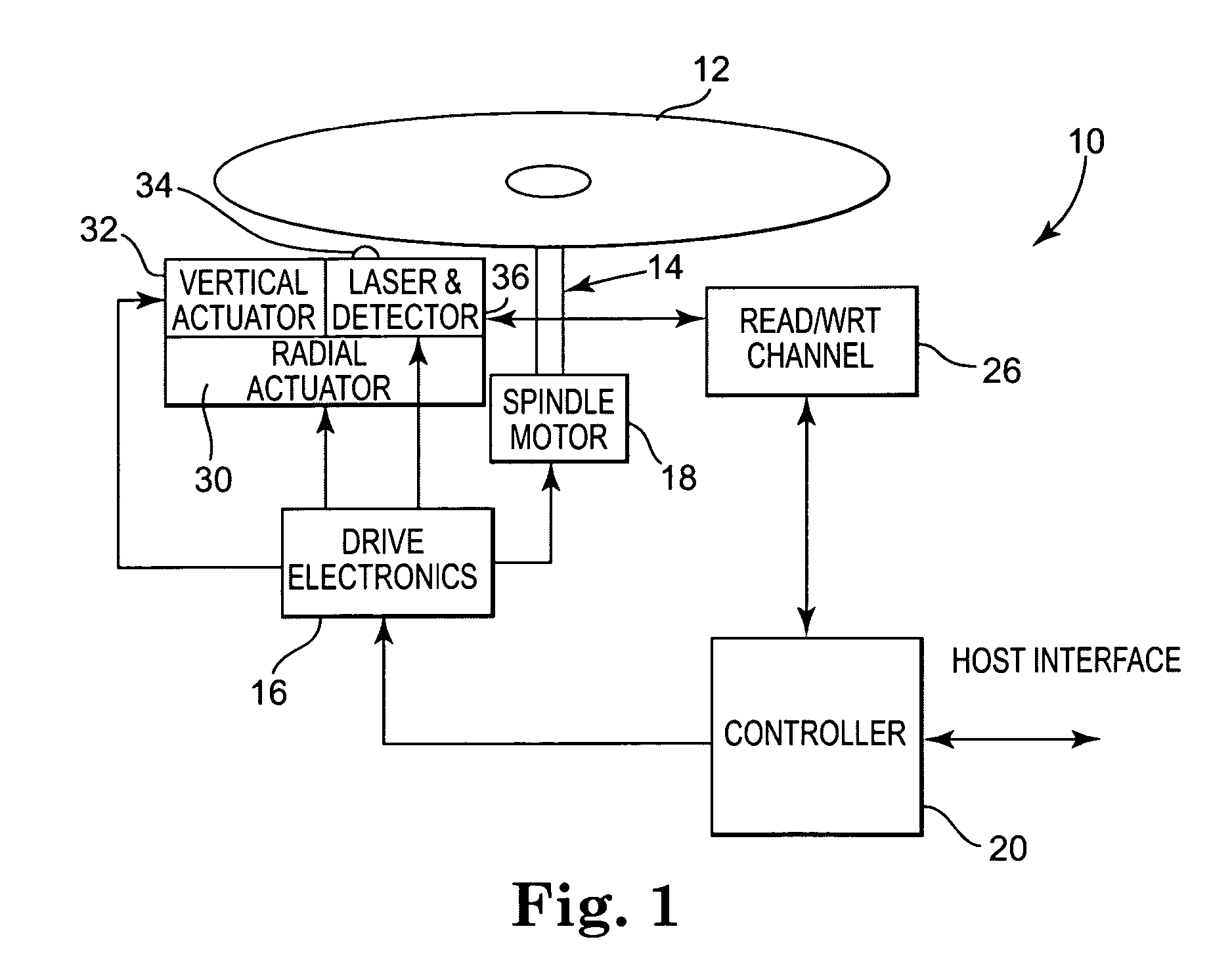
[0020] Again, the present invention relates to a data shredding methodology used within a data storage device. While the data storage device can take many forms, one exemplary system is shown in FIG. 1. Data storage device 10 utilizes a storage media 12, which in the preferred embodiment is an optical storage device. The use of optical storage media 12 has become well known and widely used in the industry because of its data storage capabilities and ease of access to data. In the present invention, the data storage media 12 is preferably removable, however could also be fixed within storage system 10. Storage media 12 is operably attached via a drive shaft 14 to a spindle motor 18. The drive shaft 14 is driven by spindle motor 18 which is controlled by drive electronics 16. Cooperating with drive electronics 16 are a laser assembly 36 including the laser itself (not shown), optics (not shown), and detection circuitry (not shown). Attached to laser assembly 36 are a radial actuator 3...


PUM

PropertyMeasurementUnit
areasaaaaaaaaaa
areaaaaaaaaaaa
timeaaaaaaaaaa

Abstract

Data protection and security is provided by incorporating a data shredding operation which renders data previously stored on storage media unrecoverable. In the shredding operation of the present invention, certain overhead portions of a data storage sector remain unchanged, while the data area is overwritten with a predetermined pattern. By maintaining the overhead portions of the sectors (addressing, verify and protect, error correction codes, etc.) the sectors can be easily identified as being previously shredded, thus not providing a source of possible confusion to the data storage device. Further, the data becomes unrecoverable as it has been overwritten by the predetermined pattern, which thus eliminates all previously existing transitions which contained the encoded data.

Description

CROSS REFERENCE TO RELATED APPLICATIONS [0001] This application claims the benefit of U.S. Provisional Application No. 60 / 711,471, filed Aug. 26, 2005.BACKGROUND OF THE INVENTION [0002] The present invention is directed toward a method and system to accomplish an optical disk shred operation. More specifically the method and system provides the ability for data in an optical disk sector to be shredded (destroyed) so the data is no longer recognizable. Further, the method and system allows for the identification of an intentionally destroyed area as a shredded sector when the storage system attempts to read the sector. [0003] Data security and data privacy are continuing issues in the world today. Naturally, those in the data storage industry are challenged to provide their assistance in dealing with these issues. In many situations, data storage providers receive requests from users to provide solutions which help to protect the integrity of information stored in various systems, an...

Claims


Application Information

Patent Timeline
Patent Type & Authority Applications(United States)
IPC IPC(8): G11B21/08
CPCG11B7/00458G11B7/0055G11B7/006G11B20/1217G11B2020/1222G11B2020/1232G11B2220/2541G11B2020/1285G11B2220/215G11B2220/237G11B2220/2516G11B2220/2537G11B2020/1267
Inventor SKEETER, BRUCE J.WORBY, BRIAN L.HOLSTINE, KEITH R.BOLT, DAVID A.
Owner PLASMON LMS
Why Eureka
Try Eureka