Highly controllable gas grill burner system

Inactive Publication Date: 2007-03-01
MEKO
View PDF11 Cites 18 Cited by
  • Summary
  • Abstract
  • Description
  • Claims
  • Application Information

AI Technical Summary

Benefits of technology

[0009] The invention meets the foregoing need and provides a method and apparatus for controlling cooking temperatures over a greater r

Problems solved by technology

However, if the user wants to more reliably control the heat, control the heat to a greater degree, and/or have a more even or uniform heat, then the typical grill is not able to provide such burner control over an entire grill area.
In this regard, the relationship between the gas flow input of the burners, the burner ports, and/or the amount of primary air intake, limit the range of control to the point that the user cannot have very

Method used


Image

  • Highly controllable gas grill burner system
  • Highly controllable gas grill burner system
  • Highly controllable gas grill burner system

Examples


Example

[0030]FIG. 3 shows a second embodiment of the invention employing three different sets of burners with three different valves constructed according to the principles of the invention. In this regard, FIG. 3 shows three different interdigitaly arranged burner sets B1, B2, and B3. A valve 240 provides cooking fuel to burner set B1 including burners 202, 210, 218 and 226. The burners 202, 210, 218, and 226, together, in conjunction with the valve 240, provide a medium temperature cooking. Another valve 242 provides a low temperature source of cooking fuel to the burner set B2 including burners 206, 214, and 222. Finally, a valve 244 provides the highest flow of fuel to the burner set B3 including burners 204, 208, 212, 216, 220, and 224. As shown in the FIG. 3 embodiment, the burner arrangements across the entire grill area 270 are somewhat uniform. However, it is contemplated that a more or less uniform arrangement of burners may also be employed. Additionally, the above-noted use of ...


PUM


Abstract

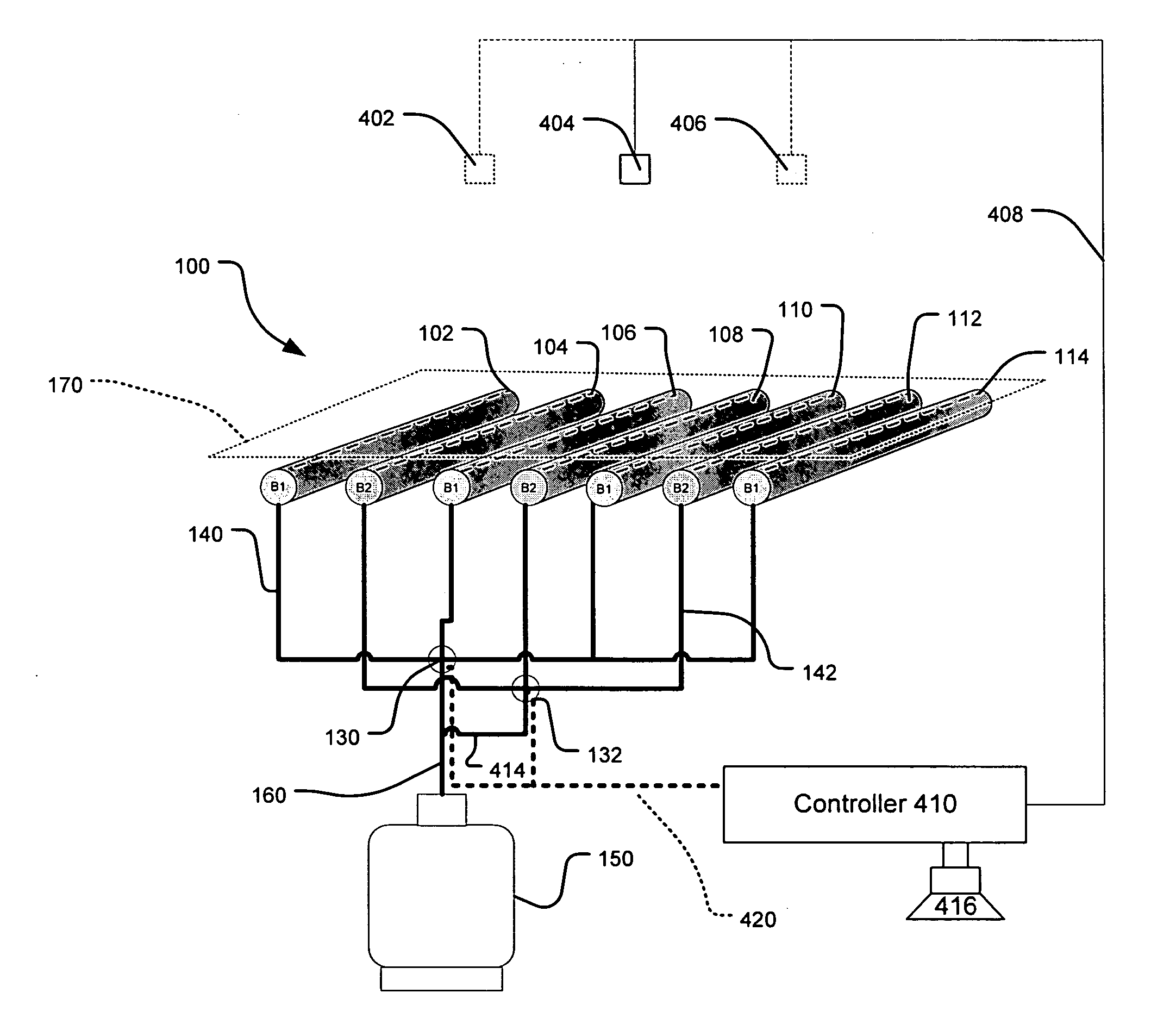
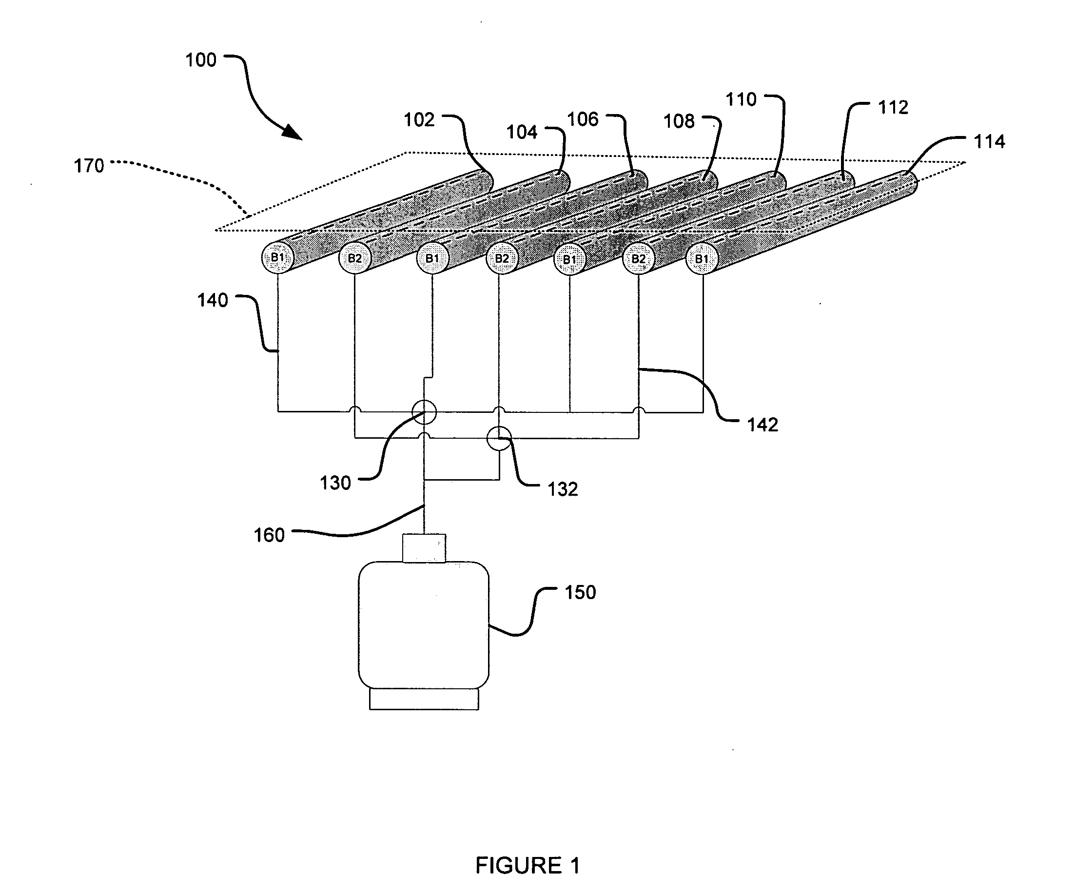
A grill for cooking includes a first set of burners and a second set of burners wherein at least one burner of the first set of burners is interdigitally arranged with burners of the second set of burners. The grill further includes a first valve that controls a flow of fuel to the first set of burners and a second valve that controls a flow of fuel to the second set of burners.

Description

CROSS-REFERENCE TO RELATED APPLICATIONS [0001] This application claims priority under 35 U.S.C. §119(e) to provisional U.S. Patent Application No. 60 / 711,674, filed on Aug. 29, 2005, the disclosure of which is expressly incorporated by reference herein in its entirety.BACKGROUND OF THE INVENTION [0002] 1. Field of the Invention [0003] The invention is directed generally to a method and apparatus for controlling a grill cooking temperature with higher accuracy and over a greater grill area. [0004] 2. Related Art [0005] The majority of gas grills typically have two to six main burners. Each of these burners is controlled by a single valve, which controls the gas flow to a particular burner in a particular grill area. The remaining burners are also each controlled by a valve. If a user of the grill wants high heat over the entire grill area, this system is sufficient to provide high heat when the valves are all turned completely on and all the main burners are operated at the same time...

Claims


Application Information

Patent Timeline
IPC IPC(8): F23N1/02F23N5/00F23Q9/00F23Q9/08
CPCA47J37/0713F23N1/002F23N5/02F23N2041/08F23N2025/08F23N2037/02F23N2023/08F23N2223/08F23N2225/08F23N2237/02F23N2241/08
Inventor HUFF, G.L.
Owner MEKO
Why Eureka
Try Eureka