High-frequency receiver

a receiver and high-frequency technology, applied in the field of high-frequency receivers, can solve the problems of abnormal input signals and abnormal reception of signals, and achieve the effects of suppressing signal distortion, improving interference resistance characteristics, and suppressing nois

Inactive Publication Date: 2007-03-01
PANASONIC CORP
View PDF7 Cites 12 Cited by
  • Summary
  • Abstract
  • Description
  • Claims
  • Application Information

AI Technical Summary

Benefits of technology

[0027] With this configuration, in a strong electric area having a high possibility that a strong interference signal is received, the gain of first amplifying circuit is controlled to be smaller by the gain switch signal from gain switch controller. Therefore, it is possible to output a signal with suppressed signal distortion from high-frequency receiving unit.
[0028] Meanwhile, in a weak electric area, first amplifying circuit is operated with a maximum gain by the gain switch signal from gain switch controller. Therefore, it is possible to output a signal with suppressed noise from high-frequency receiving unit.
[0029] In this way, the operation state of first amplifying circuit is switched by gain switch controller, which make it possible to provide a high-frequency receiver capable of improving the interference-resistant characteristic in a strong electric field having a high possibility that a strong interference signal is received and reception sensitivity in a weak electric field area. In particular, the high-frequency receiver according to the aspect can stably receives a signal under a circumstance in which a reception condition is remarkably changed, such as a case of receiving, for example, digital broadcast signal during movement.

Problems solved by technology

However, in known high-frequency receiver 1, if a high-level interference signal is input to input terminal 2a in a frequency area close to a desired input signal, amplifying circuit 5 or mixer 7 abnormally operates due to the high-level interference signal, which makes an input signal abnormal.
Accordingly, upon reception of the digital broadcast signal, a high-level analog broadcast signal may interfere with the digital broadcast signal, which results in the abnormal reception of signals.

Method used


Image

  • High-frequency receiver
  • High-frequency receiver
  • High-frequency receiver

Examples


first embodiment

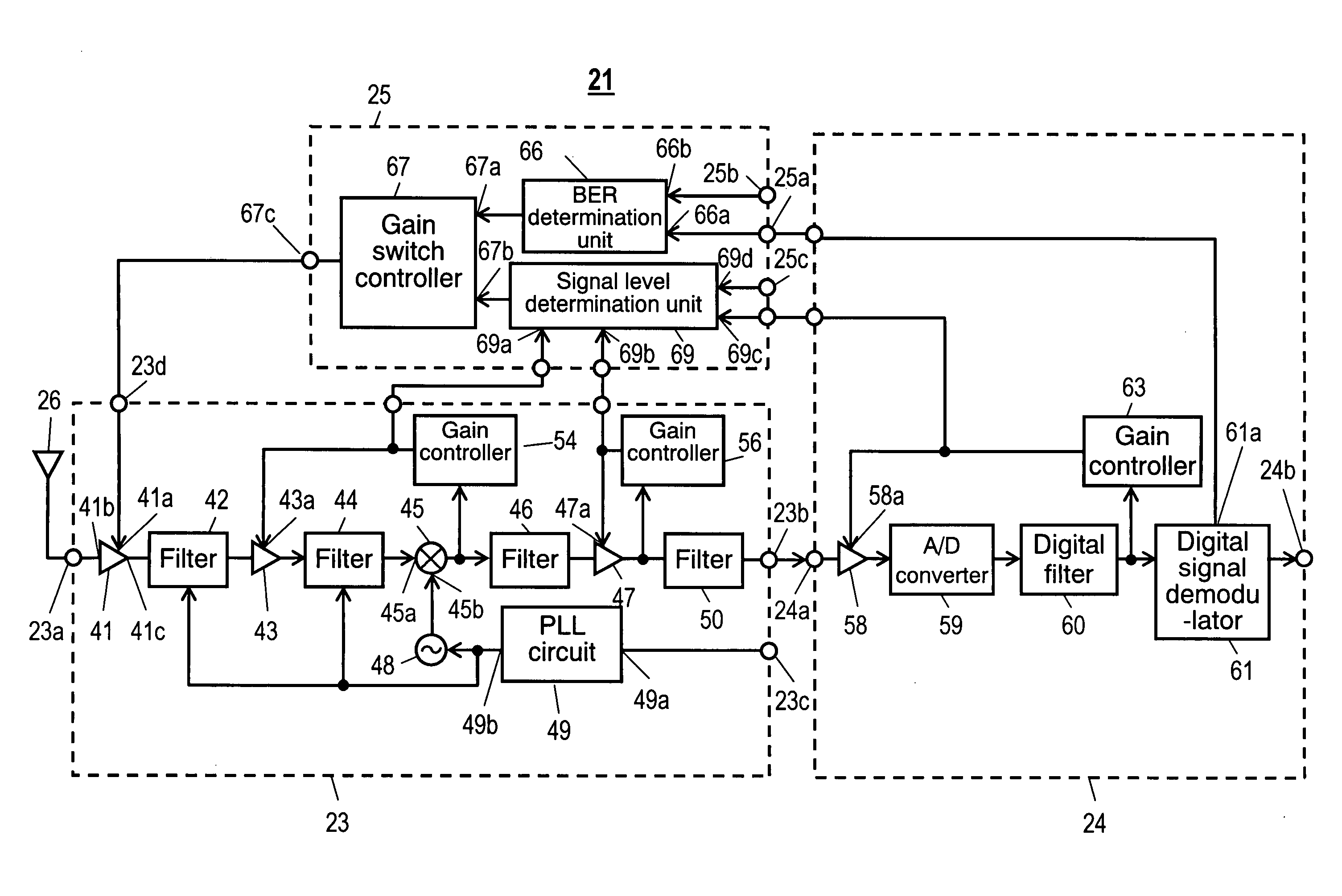
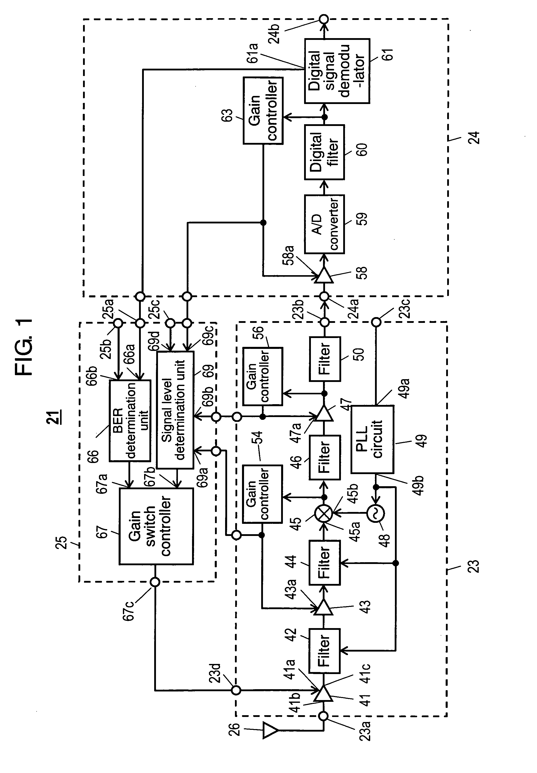
[0037] A first embodiment of the invention will be described with reference to FIG. 1. FIG. 1 is a block diagram showing high-frequency receiver 21. In the first embodiment, high-frequency receiver 21 receiving a digital TV broadcast signal will be described as an example.

[0038] High-frequency receiver 21 mainly includes high-frequency receiving unit 23, demodulating unit 24 connected to the output terminal of high-frequency receiving unit 23, and a gain switch control unit 25 controlling high-frequency receiving unit 23.

[0039] First, the configuration of high-frequency receiving unit 23 will be described. High-frequency receiving unit 23 has first input terminal 23a connected to antenna 26 and first output terminal 23b. Between first input terminal 23a and first output terminal 23b, amplifying circuit 41 amplifying a signal, filter 42 suppressing interference signal components, amplifying circuit 43 of which the gain can be controlled by gain control input 43a, filter 44 connecte...

second embodiment

[0102]FIGS. 3A and 3B relate to a second embodiment of the invention. In particular, FIGS. 3A and 3B show amplifying circuits 71 and 72 as specific examples of amplifying circuit 41, respectively. The same components in FIGS. 3A and 3B as those in FIG. 1 have the same reference numerals and a description thereof will be omitted.

[0103] In amplifying circuit 71 shown in FIG. 3A, amplifier 71a is provided between input terminal 41b and output terminal 41c. Amplifier 71 is connected in parallel with a series circuit of electronic switch 71b and resistance attenuator 71c. Further, gain switch control terminal 23d is connected to gain control input terminal 41a for controlling the opening / closing of electronic switch 71b.

[0104] When amplifying circuit 71 having the above-mentioned configuration receives a gain switching signal through gain control input terminal 41a, power supply to amplifier 71a starts, and electronic switch 71b is opened. Therefore, a signal input to input terminal 41...

third embodiment

[0113]FIG. 4 shows high-frequency receiver 121 according to a third embodiment of the invention. The same components in FIG. 4 as those in FIG. 1 have the same reference numerals, and a description thereof will be omitted.

[0114] In the first embodiment (see FIG. 1) described above, the gains of amplifying circuits 43, 47, and 58 are controlled by gain controllers 54, 56, and 63, respectively, and the gain control voltages output from these gain controllers are input to input terminals 69a, 69b, and 69c of signal level determination unit 69.

[0115] The third embodiment is different from the first embodiment in that: gain controller 63 is not used or amplifying circuit 158 with a constant gain is used instead of amplifying circuit 58; an output signal of digital filter 60 is input to an input terminal of gain controller 156; the gains of amplifying circuits 43 and 147 are controlled by gain controllers 54 and 156, respectively; and gain control voltages output from gain controllers 5...


PUM


Abstract

A high-frequency receiver capable of improving both an interference-resistant characteristic and reception sensitivity is provided. A gain switch control unit includes: a signal level determination unit comparing a gain control voltage of an amplifying circuit with a reference voltage; and a gain switch controller provided between an output terminal of the signal level determination unit and a gain control input terminal provided to an amplifying circuit for gain control. When receiving a signal in a strong electric field area having a high possibility that a strong interference signal exists, a gain of the amplifying circuit is set to be smaller than that in a case of receiving a signal in a weak electric field area by a gain switch signal output from the gain switch controller.

Description

BACKGROUND OF THE INVENTION [0001] 1. Technical Field [0002] The present invention relates to a high-frequency receiver that enables good reception even in a reception area where there is a high possibility that a strong interference signal is received or an area where a television broadcast signal is weak. [0003] 2. Background Art [0004]FIG. 6 shows a known high-frequency receiver. High-frequency receiver 1 includes high-frequency receiving unit 2 and demodulating unit 3 connected to an output terminal of high-frequency receiving unit 2. [0005] In high-frequency receiving unit 2, a signal received by antenna 4 is input to amplifying circuit 5 through input terminal 2a. Amplifying circuit 5 amplifies the input signal and outputs the amplified signal as an output signal. The output signal is gain-controlled by amplifying circuit 6 and is then input to first input terminal 7a of mixer 7. An output signal of oscillator 8 is input to second input terminal 7b of mixer 7. Mixer outputs a ...

Claims


Application Information

Patent Timeline
Patent Type & Authority Applications(United States)
IPC IPC(8): H04B7/00H04B1/06H03G3/20H04B1/10H04B1/16H04N5/44
CPCH03G3/3078H04B1/16H04B1/06H04N5/44
Inventor FUJISHIMA, AKIRAHIBINO, YASUHIROFURUSAWA, TOSHIHIROKITAMURA, HIROKAZUUMEDA, TAKASHIKOYAMA, TAKAHIRO
Owner PANASONIC CORP
Why Eureka
Try Eureka