
Automatic vehicle gearshift transmission

a transmission and automatic technology, applied in the direction of engine-driven generators, transportation and packaging, transportation, etc., can solve the problems of affecting the traction force of the drive train,

Inactive Publication Date: 2007-03-01
ZF FRIEDRICHSHAFEN AG
View PDF5 Cites 12 Cited by
  • Summary
  • Abstract
  • Description
  • Claims
  • Application Information

AI Technical Summary

Benefits of technology

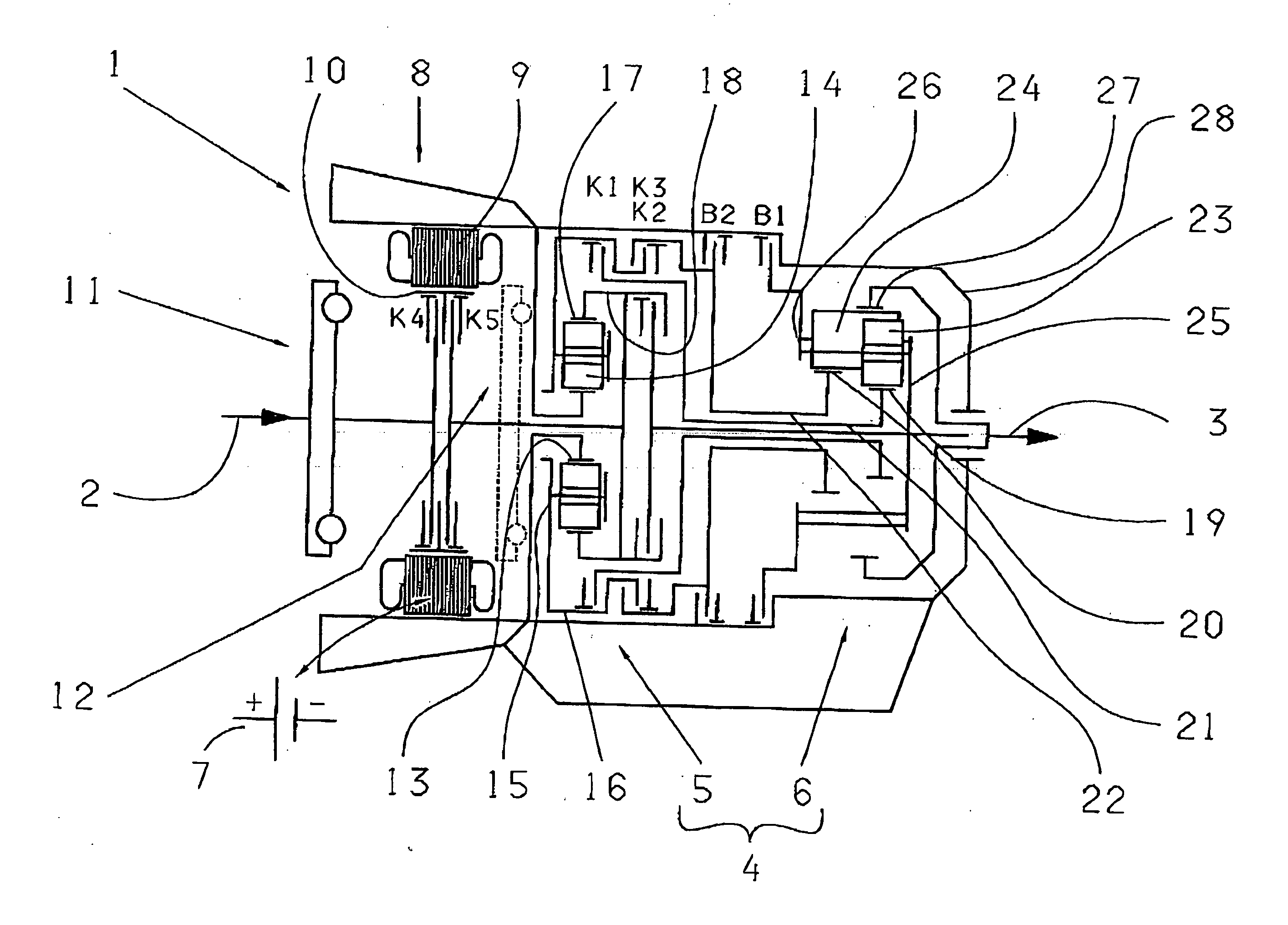
[0009] Advantageously, the transmission according to the invention saves components compared with the closest prior art. For example, a starting brake previously provided on the input side is not needed here. Furthermore, instead of the previously used two input shafts in the transmission, only one input shaft is needed. Thanks to this the transmission can advantageously be designed such that both the combustion engine and also the electric machine can be connected via two clutches or via one clutch to the annular gear of the first planetary gearset. This on the one hand gives a transmission with a simplified starter and / or generator and recuperation capacity or one with simpler boost operation, and on the other hand distinctly reduces the structural space occupied by the transmission and cuts its production costs.
[0011] Alternatively, depending on the application situation in each case, it can also be advantageous to make the clutches such that they engage with positive locking, again with the two shift elements being actuated independently of one another.
[0012] It is also proposed that one of the two shift elements is made as a freewheel element, or that a further shift element is provided and this is made as a freewheel element. This makes it possible for example to have an emergency running function.
[0017] As a particularly simple and therefore inexpensive structure of the vehicle transmission, the solar gear is arranged fixed to the housing.

Problems solved by technology

Under certain circumstances, during this there may occur interruptions of the traction force in the drive train which, though slight, are nevertheless undesired as such.

Method used


Image

  • Automatic vehicle gearshift transmission
  • Automatic vehicle gearshift transmission

Examples


Embodiment Construction

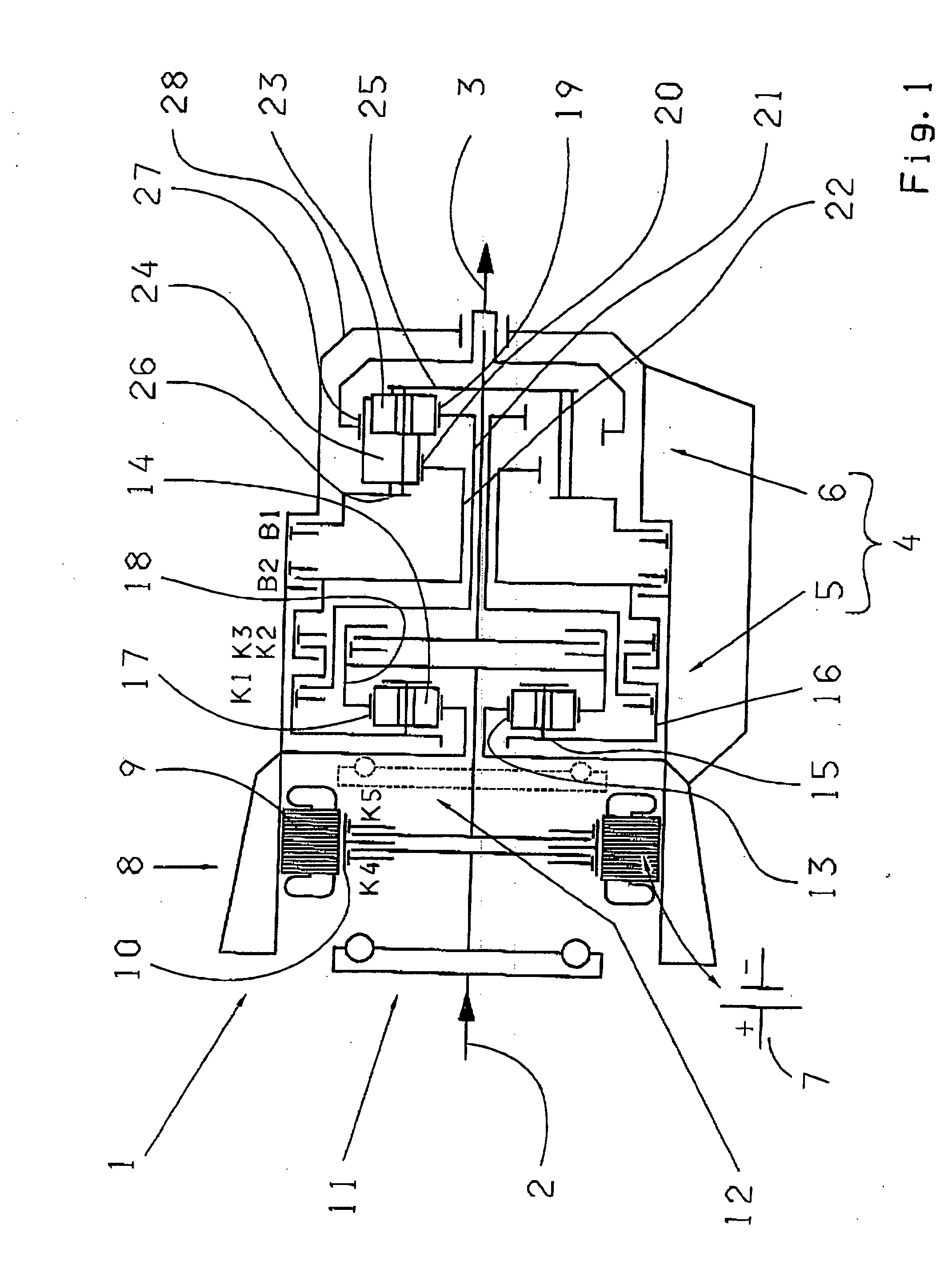
[0025] An automatic vehicle gearshift transmission 1 is part of a parallel-hybrid drive train of a motor vehicle, no more of which is shown. This transmission 1 comprises a drive input shaft 2 connected on the input side, for example via a torsion damper 11, to an internal combustion engine of the drive train (not shown).

[0026] On the output side, a drive output shaft 3 is provided on the transmission 1, which can be connected to at least one vehicle axle in order to transmit a drive torque. Between the two said shafts 2 and 3 is arranged a mechanical gearshift 4 consisting of a first transmission stage (first planetary gearset 5) and a second transmission stage (second planetary gearset 6), several clutches K1, K2, K3 and two brakes B1 and B2.

[0027] The first transmission stage consists for example of a single planetary gearset 5 arranged upstream from a second transmission stage consisting of a Ravigneaux gearset 6. Such an arrangement enables for example a range-change automati...


PUM


Abstract

An automatic gearshift transmission with a drive input shaft and a drive output, a mechanical gearshift with first and second planetary gearsets, the first planetary gearset being a single planetary gearset downstream from which is connected a double planetary gearset, with several shift elements, including clutches and brakes and with an electric machine provided as a starter and / or generator and / or for the at least partial electric operation of a vehicle, such that the electric machine can be connected by way of a fourth clutch to the combustion engine and by way of a fifth clutch to a first shaft of the first planetary gearset. The combustion engine can be connected by way of the fourth and fifth clutches to the annular gear of the first planetary gearset and / or the electric machine can be connected by way of the fifth clutch to the annular gear of the first planetary gearset.

Description

[0001] This application claims priority from German Application Serial No. 10 2005 040 769.2 filed Aug. 29, 2005. FIELD OF THE INVENTION [0002] The invention concerns an automatic vehicle gearshift transmission. BACKGROUND OF THE INVENTION [0003] From the generically similar DE 101 40 424 A1 a parallel-hybrid drive train of a motor vehicle is known. Besides the internal combustion engine this drive train comprises an automatic gearshift transmission which has two drive input shafts that can be connected to the combustion engine and a drive output shaft that can be coupled to at least one drive axle of the motor vehicle, as well as a mechanical gearshift with a first and a second planetary gearset, several clutches, several brakes and an electric machine. The electric machine can be operated as a starter / generator and / or for the continuously variable adjustment of the transmission and / or to drive the motor vehicle under electric power. If the driver so wishes, acceleration can take p...

Claims


Application Information

Patent Timeline
Patent Type & Authority Applications(United States)
IPC IPC(8): F16H3/72B60K6/26B60K6/38B60K6/40B60K6/442B60K6/445B60L50/16
CPCB60K6/26B60K6/38B60K6/40B60K6/48F16H3/663Y02T10/6221F16H2200/2007F16H2200/2023F16H2200/2043F16H2200/2097F16H2200/0052Y02T10/62
Inventor GUMPOLTSBERGER, GERHARDREISCH, MATTHIASKILIAN, STEFAN
Owner ZF FRIEDRICHSHAFEN AG
Learn More