Rotary wing aircraft flight control system with a proximity cueing and avoidance system

Active Publication Date: 2007-03-01
SIKORSKY AIRCRAFT
View PDF12 Cites 22 Cited by
  • Summary
  • Abstract
  • Description
  • Claims
  • Application Information

AI Technical Summary

Benefits of technology

[0014] In an aircraft flight control system that utilizes a full authority Fly-By-Wire (FBW) control system, the obstacle cueing and avoidance system produces a command signal which is communicated to a servo as well as to a FBW control law logic. As with the partial authority system, the servo generates an input to essentially stiffen the input control device to provide a feedback cue to the pilot in a direction, which tends to preclude the aircraft from moving in a direction towards the obstacle. That is, the feedback counteracts the pilot's input so that the aircraft tends not to move. Alternatively, the servo may generate an input that tends to move the aircraft in a direction away from the detected obstacle so as to minimize

Problems solved by technology

Disadvantageously, these ground obstacles alert systems may be just one of many warning systems incorporated into the aircraft such that the pilot may miss the al

Method used


Image

  • Rotary wing aircraft flight control system with a proximity cueing and avoidance system
  • Rotary wing aircraft flight control system with a proximity cueing and avoidance system
  • Rotary wing aircraft flight control system with a proximity cueing and avoidance system

Examples


Example

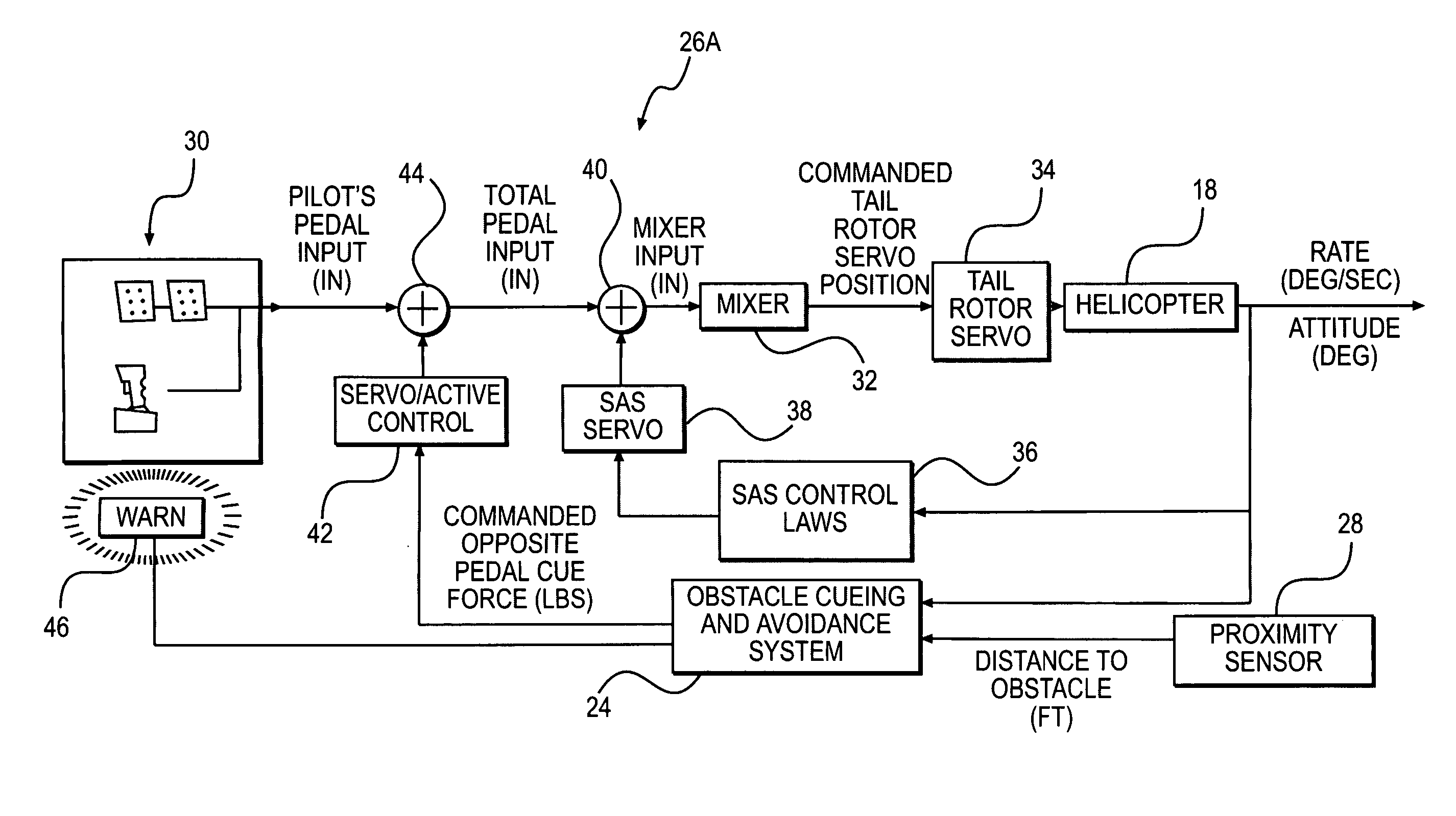
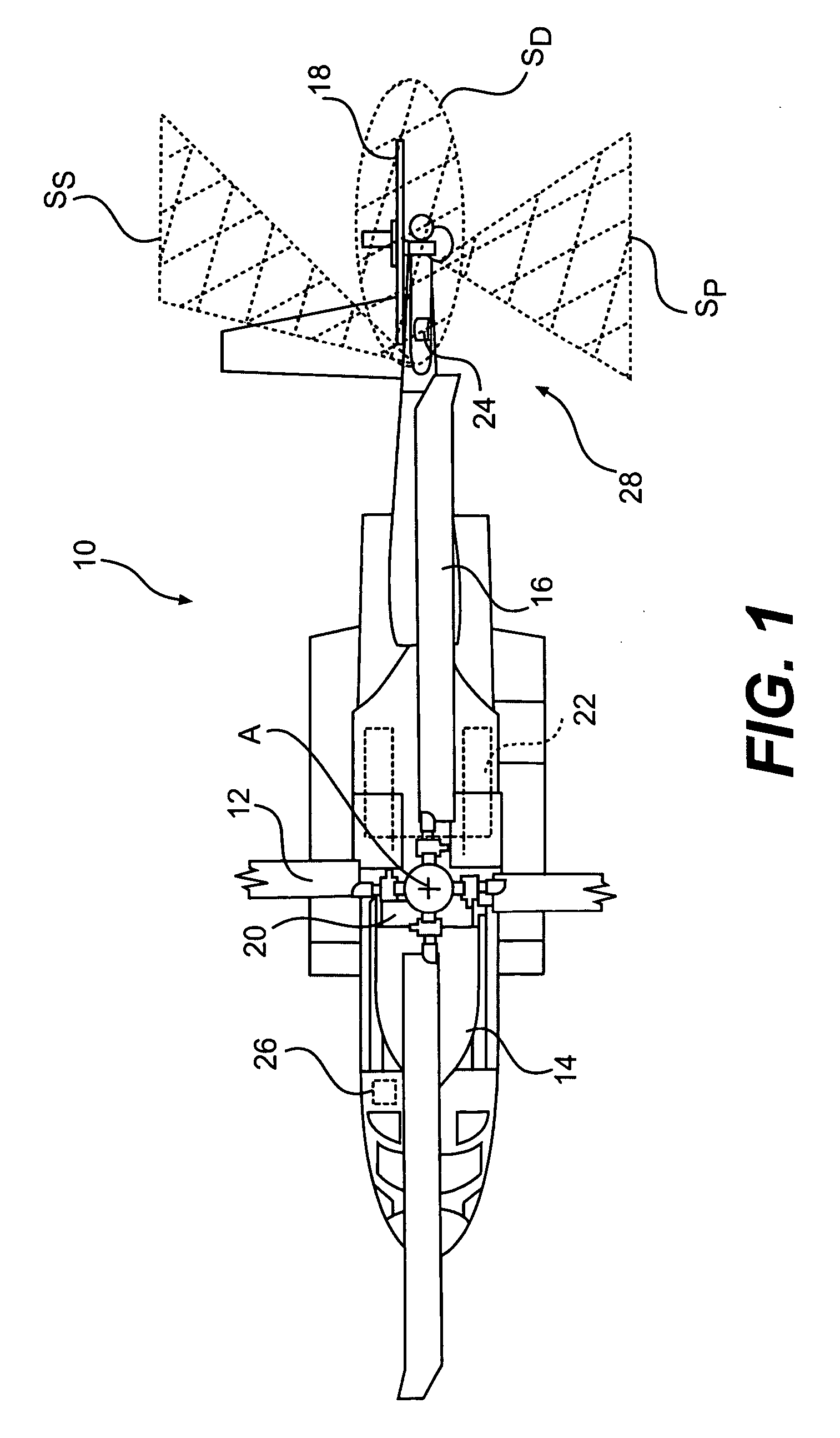
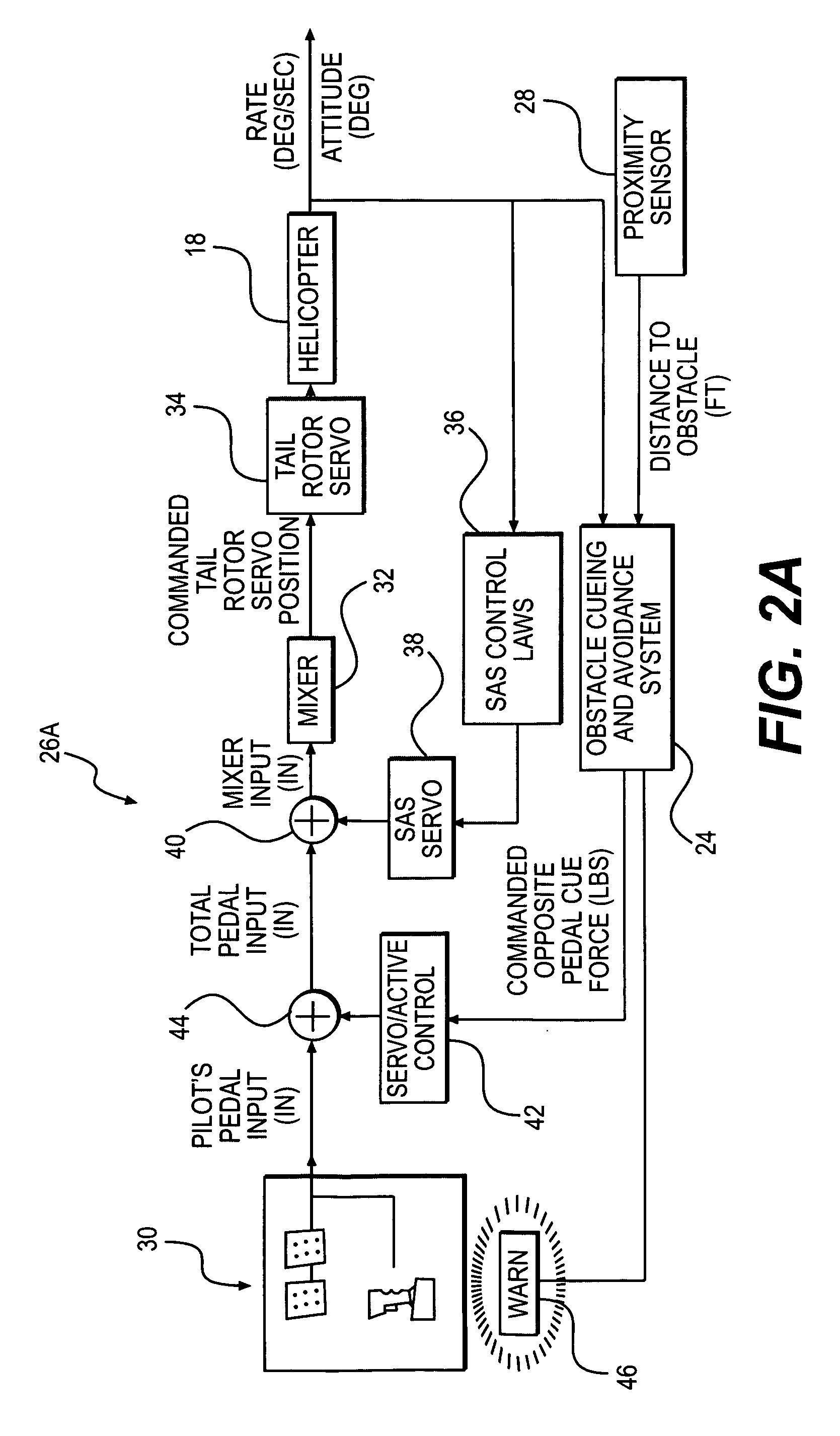
[0020] Although the present invention will be described in terms of an obstacle avoidance system for use with a rotary wing aircraft in order to minimize the likelihood of contact between the aircraft, specifically the tail of the rotary wing aircraft, and a nearby obstacle, the present invention is easily adaptable to prevent contact between a nearby obstacle and any other portion of the aircraft, for example, the fuselage, main rotor system, tail rotor system, etc. It should be further understood that the present invention is also easily adaptable for use with other apparatuses, structures, etc. where avoidance of contact with a nearby obstacle is desired.

[0021] The present invention is directed to an obstacle avoidance system. Preferably, as will be described in greater detail below, the obstacle avoidance system includes an input control device, which may be in the form, for example, of anti-torque pedals, a flight control stick, etc. The input control device being operable to ...


PUM


Abstract

An obstacle avoidance system according to the present invention may include an input control device, a sensor suite, and a communication feedback loop. The input control device is preferably operable to create a first force, while the sensor suite is configured to detect nearby obstacles, and the communication feedback loop is in communication with the input control device and the senor suite so that said communication feedback loop is operable to generate a command signal in response to detection of a nearby obstacle. The command signal being operable to cause an actuator to generate a second force different from said first force. Preferably, the obstacle avoidance system is used in combination with an apparatus, such as a rotary wing aircraft, wherein the input control device at least partially controls the movement of the apparatus in response to a user's input. The user's input tending to cause the first force to move the apparatus in a first direction. The sensor suite being preferably mounted to the apparatus in order to detect nearby obstacles which may contact the apparatus if the apparatus is moved in the first direction. The communication feedback loop at least partially augmenting the user's input such that the second force tends to preclude the apparatus from moving in the first direction and thus tends to preclude the apparatus from contacting the detected obstacle. More preferably, the second force tends to cause the apparatus to move in a second direction different from the first direction and away from the detected obstacle.

Description

BACKGROUND OF THE INVENTION [0001] The present invention relates to an obstacle avoidance system. More particularly, the present invention relates to an obstacle avoidance system, which may be incorporated into the flight control system of a rotary wing aircraft to minimize the likelihood that a portion of the aircraft will contact a detected obstacle. [0002] Various systems have been developed to minimize the likelihood that a rotary wing aircraft will contact obstacles, such as telephone lines, etc., while flying at low levels. Current techniques include active electronic systems such as microwave and millimeter wave radar systems, passive systems which detect the magnetic flux from a live transmission line, and mechanical systems which cut the wires upon contact. [0003] Other systems are designed to warn pilots of ground obstacles that may be located around the periphery of the rotary-wing aircraft during, for example, hover, landing, etc. For example, in one such system, a laser...

Claims


Application Information

Patent Timeline
IPC IPC(8): G01C5/00G08G1/16G01S13/933G01S17/933
CPCG01S13/9303G01S17/933G08G5/045G08G5/0021G05D1/0858G01S13/933
Inventor MATUSKA, DAVID G.SAHASRABUDHE, VINEETANTTILA, DONALD S.
Owner SIKORSKY AIRCRAFT
Why Eureka
Try Eureka