Storage system for copying data and storing in a plurality of storage devices

a storage system and data technology, applied in error detection/correction, program control, instruments, etc., can solve the problems of insufficient study for improving convenience when using a plurality of storage devices, and the user's setting in many cases requires a great deal of effort, so as to reduce the effort of users and improve convenience.

Inactive Publication Date: 2007-03-01
HITACHI LTD
View PDF12 Cites 49 Cited by
  • Summary
  • Abstract
  • Description
  • Claims
  • Application Information

AI Technical Summary

Benefits of technology

[0007] An object of the present invention is to provide technology capable of reducing the effort of users required for setting the copy destination storage area. Another object is to provide a technology capable of improving convenience when using a plurality of storage devices for storing copy data.

Problems solved by technology

However, the settings in many cases require a great deal of effort by the user.
Also, not enough study had been done for improving the convenience when using a plurality of storage devices for storing copy data.

Method used


Image

  • Storage system for copying data and storing in a plurality of storage devices
  • Storage system for copying data and storing in a plurality of storage devices
  • Storage system for copying data and storing in a plurality of storage devices

Examples


first embodiment

A. First Embodiment

A1. Device Constitution

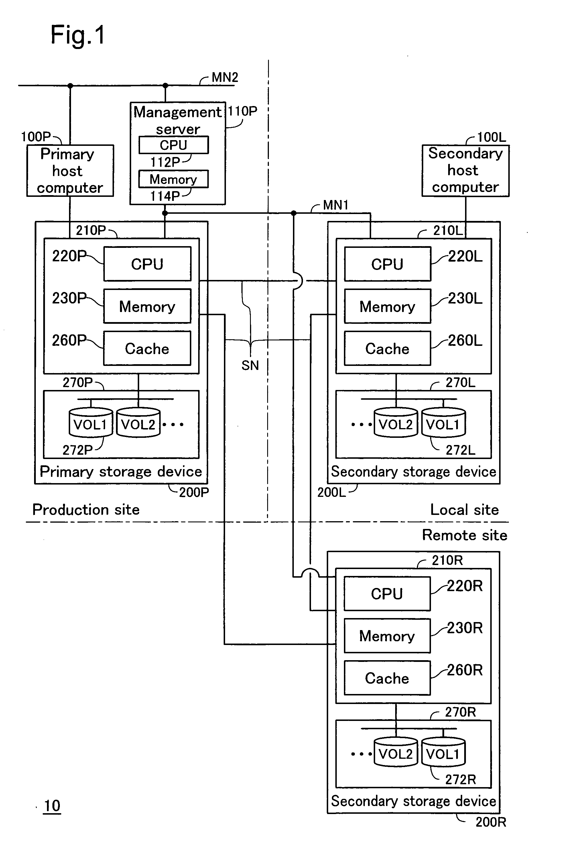
[0072]FIG. 1 is an explanatory drawing showing the hardware constitution of the data processing system as an embodiment of the present invention. This data processing system 10 comprises two host computers 100 (100P, 100L), three storage devices 200 (200P, 200L, and 200R), and a management server 110P. Note that the overall three storage devices 200 (200P, 200L, and 200R) and the management server 110P correspond to the “storage system.”

[0073] The primary host computer 100P, the primary storage device 200P, and the management server 110P are installed at the production site for performing the data processing operation. The secondary host computer 100L and the secondary storage device 200L are installed at the local site near the production site. The secondary storage device 200R is installed at a remote site that is distant from the production site. Hereafter, the production site is also called the “primary site.”

[0074] With this specificat...

second embodiment

B. Second Embodiment

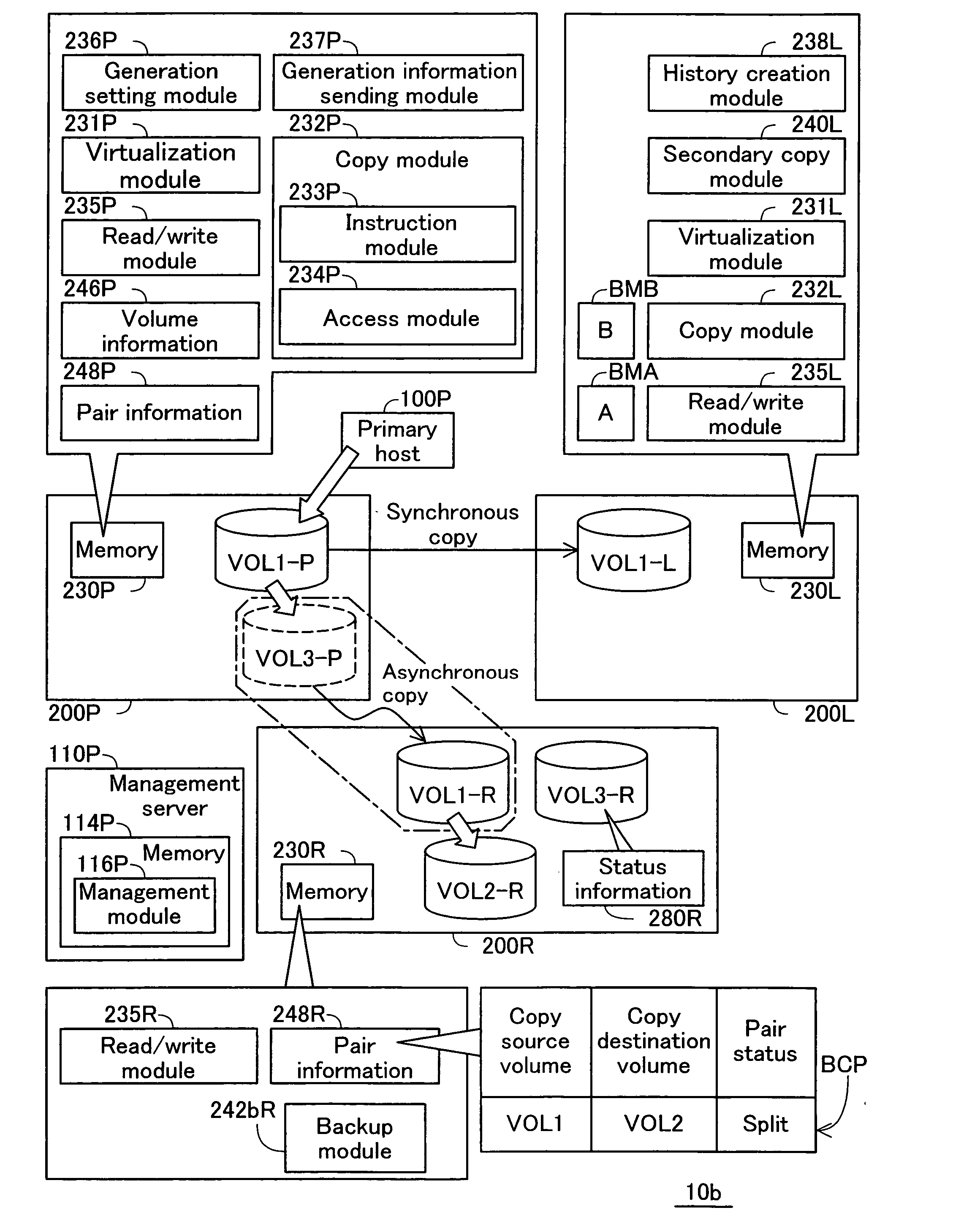
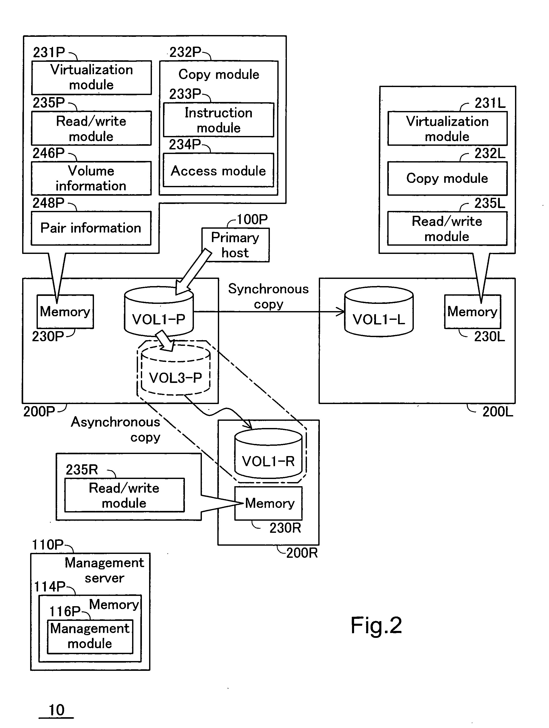
[0109]FIG. 7 is an explanatory drawing showing the constitution of the data processing system 10a of the second embodiment. The hardware constitution of the data processing system 10a is the same as that of the data processing system 10 shown in FIG. 1. However, the functional constitution of each storage device 200 is different from that of the data processing system 10 shown in FIG. 2. The difference for each storage device 200 is as follows.

(1) Difference for the Primary Storage Device 200P:

[0110] The memory 230P further stores the generation setting module 236P and the generation information sending module 237P.

(2) Difference for the Synchronous Storage Device 200L:

[0111] The memory 230L further stores the history creation module 238L, the secondary copy module 240L, the first bitmap BMA, and the second bitmap BMB.

(3) Difference for the Asynchronous Secondary Storage Device 200R:

[0112] The memory 230R further stores the history creation module 238R, ...

third embodiment

C. Third Embodiment

[0185]FIG. 26 is an explanatory drawing showing the process that the copy module 232P executes at the start of resynchronization of the asynchronous copy pair CP2 for the third embodiment. There are two differences from the second embodiment described above. The first difference is that the process at the start of this resynchronization is switched according to the presence or absence of problems with the synchronous copying. The other procedures of the writing process are the same as the example shown in FIG. 10 and FIG. 11. The second difference is that a new condition is added to the conditions for selecting the differential bitmap. The constitution of the data processing system is the same as the data processing system 10a shown in FIG. 7.

[0186] When the copy module 232P (FIG. 7) receives the resynchronization instructions from the management server 110P at step S300 (FIG. 11, step M144), a judgment is made of whether or not there is a problem with synchronou...


PUM


Abstract

A storage system comprises a primary storage device having a primary storage area, a first secondary storage device having a first secondary storage area, and a second secondary storage device having a second secondary storage area. Responsive to host request from a host computer, the primary storage device writes requested host data to the primary storage area. Furthermore the primary storage device sends a first and second copy request to the first and second secondary storage devices, respectively, to store copy data in the first and second secondary storage areas, the first and second copy request containing the copy data which is a copy of the host data. Here the second secondary storage area is identified by a virtual identifier used to identify the second secondary storage area as the virtual storage area within the primary storage device.

Description

CROSS-REFERENCE TO RELATED APPLICATIONS [0001] The present application claims the priority based on Japanese Patent Application No. 2005-253352 filed on Sep. 1, 2005, the disclosure of which is hereby incorporated herein by reference in its entirety. BACKGROUND [0002] 1. Field of the Invention [0003] The present invention relates to a storage system for copying data and storing in a plurality of storage devices. [0004] 2. Description of the Related Art [0005] Remote copy technology is known for a data processing system comprising a storage system having a plurality of storage devices, and a host computer (See, for example, JP2005-78453A, JP2004-5370A, and JP2000-242437A). Remote copy is technology for copying data stored in a storage area included in one storage device to a storage area included in another storage device within the storage system. By using this remote copy technology, it is possible to continue work on the data processing system by using the data stored in the other...

Claims


Application Information

Patent Timeline
Patent Type & Authority Applications(United States)
IPC IPC(8): G06F12/16
CPCG06F3/0605G06F11/2058G06F2201/815G06F11/2074G06F11/2076G06F11/2064
Inventor ARAKAWA, HIROSHININOSE, KENTADEGUCHI, AKIRAHOMMA, HISAOOKUMOTO, KATSUHIRO
Owner HITACHI LTD
Why Eureka
Try Eureka