Semifinished flat tube, process for producing same, flat tube, heat exchanger comprising the flat tube and process for fabricating the heat exchanger

a technology flat tubes, which is applied in the direction of tubular elements, lighting and heating apparatus, stationary conduit assemblies, etc., can solve the problems of insufficient rigidity of semi-finished flat tubes, deformation of tubes, and insufficient semi-finished flat tubes, so as to improve rigidity, prevent deformation, and the effect of high rigidity

Inactive Publication Date: 2007-03-08
SHOWA DENKO KK
View PDF2 Cites 27 Cited by
  • Summary
  • Abstract
  • Description
  • Claims
  • Application Information

AI Technical Summary

Benefits of technology

[0012] With the first semifinished flat tube of the invention, the two third portions are welded to each other at least at longitudinal opposite end portions thereof from outside. This prevents the semifinished flat tube from opening at its opposite ends, and the opposite ends of the tubes to be used for fabricating a heat exchanger can be reliably inserted into the respective tube inserting holes of the headers. Further the third portions of each of the semifinished tubes can be brazed subsequently in the fabrication process without producing any fault. Moreover, the semifinished tube of the invention has higher rigidity than those of the prior art, and such tubes can be assembled into the heat exchanger or otherwise handled free of deformation.
[0027] With the second semifinished flat tube of the invention, the metal plate may comprise an aluminum brazing sheet having a brazing material layer over opposite surfaces thereof. When the second portions, as well as the fourth portions, are to be subsequently brazed, the brazing material layer of the metal plate is usable for brazing. This eliminates the time and labor needed for applying a brazing material separately.

Problems solved by technology

However, we have found that the semifinished flat tube has the following problems.
The aluminum plate for use in making the semifinished flat tubes is given a reduced thickness recently to obtain a condenser of reduced weight, with the result the semifinished flat tubes are insufficient in rigidity.
This results in the likelihood that the tubes will deform when the tubes are assembled into a condenser or otherwise handled.

Method used


Image

  • Semifinished flat tube, process for producing same, flat tube, heat exchanger comprising the flat tube and process for fabricating the heat exchanger
  • Semifinished flat tube, process for producing same, flat tube, heat exchanger comprising the flat tube and process for fabricating the heat exchanger
  • Semifinished flat tube, process for producing same, flat tube, heat exchanger comprising the flat tube and process for fabricating the heat exchanger

Examples


example 1

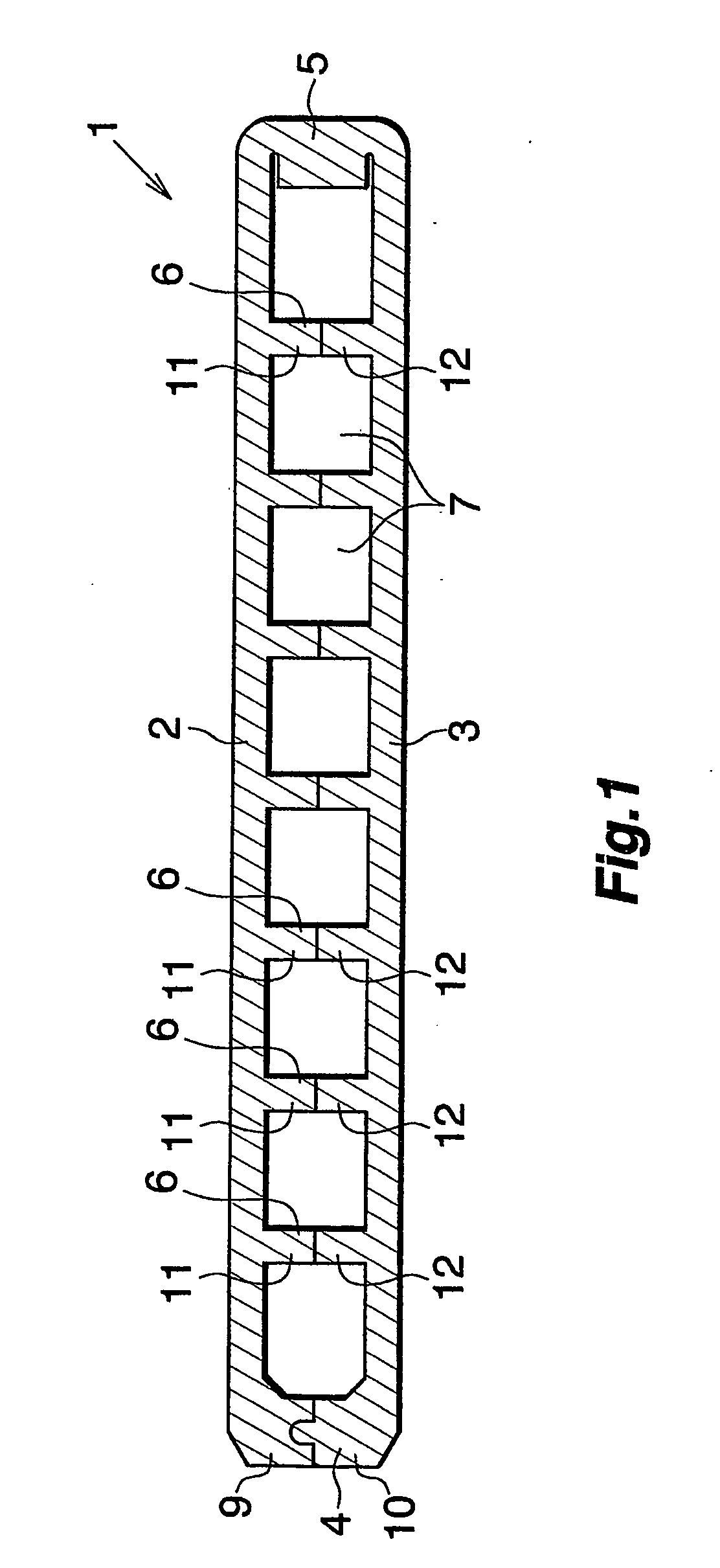
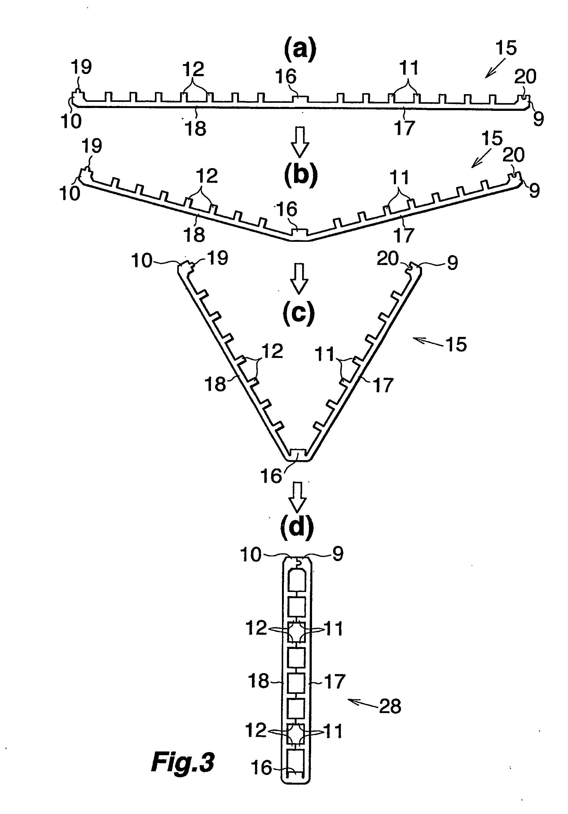
[0069] An aluminum brazing sheet made from JIS BAS211P was rolled into a metal plate 15 shown in FIG. 3, (a). The metal plate was then made into a semifinished flat tube 40 wherein two third portions 9, 10 were continuously joined to each other over the entire length thereof by laser welding as shown in FIG. 7. The laser welding conditions were: pulse width, 0.5 flat tubes 1 may be produced simultaneously with the fabrication of the condenser. More specifically, the condenser is fabricated in the following manner. First prepared are a plurality of semifinished flat tubes 30. Also prepared are a pair of aluminum headers 100, 101 each having semifinished tube inserting holes equal in number to the number of semifinished flat tubes 30, and a plurality of corrugated aluminum fins 103. The pair of headers 100, 101 are then arranged as spaced apart, the semifinished flat tubes 30 and the fins 103 are arranged alternately, and opposite ends of the semifinished flat tubes 30 are inserted in...

examples 2-9

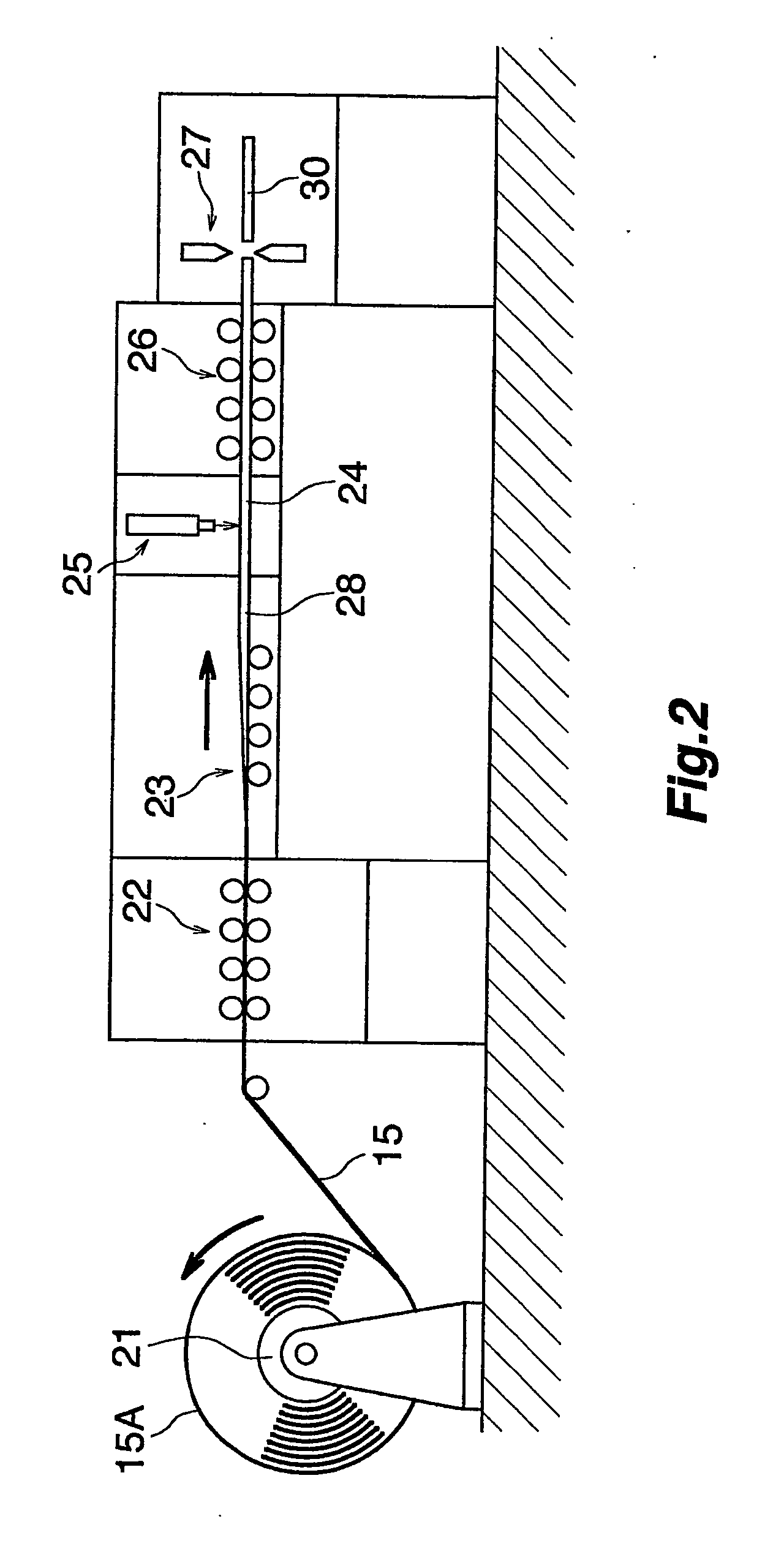
[0072] An aluminum brazing sheet made from JIS BAS211P was rolled into a metal plate 15 shown in FIG. 3, (a). The metal plate was then made into a semifinished flat tube 30 wherein two third portions 9, 10 were intermittently joined to each other at a spacing longitudinally thereof by laser welding as shown in FIGS. 4 to 6. The laser welding conditions were: pulse width, 0.5 ms; frequency, 66.7 Hz; pulse energy, 3 J; assist gas, none; work moving velocity, 200 m / min. The laser welds were 0.6 mm in nugget diameter D and 0.2 mm in the depth of penetration d. The weld laser 31 positioned at each of opposite end portions of the third portions 9, 10 was at a distance L of 15 mm from the longitudinal end of the third portion. The tubes 30 of the examples were produced with varying weld pitches P. The semifinished flat tubes 30 were 1.1 mm in the combined height H of the two third portions 9, 10, 0.4 mm in the thickness t of each of the third portions 9, 10, and 16 mm in the overall width....

examples 10-15

[0075] An aluminum brazing sheet made from JIS BAS211P was rolled into a metal plate 15 shown in FIG. 3, (a). The metal plate was then made into a semifinished flat tube 30 wherein two third portions 9, 10 were intermittently joined to each other at a spacing longitudinally thereof by laser welding as shown in FIGS. 4 to 6. The laser welding conditions were: pulse width, 0.5 ms; frequency, 66.7 Hz; pulse energy, 3 J; assist gas, none; work moving velocity, 200. m / min. The laser weld 31 positioned at each of opposite end portions of the third portions 9, 10 was at a distance L of 15 mm from the longitudinal end of the third portion. The pitch P of all the welds was 30 mm. The tubes 30 of the examples were produced with varying values for D / H ahd for d / t wherein D is the nugget diameter of laser the welds 31, H is the combined height of the two third portions 9, 10, d is the depth of penetration of the laser welds 31, and t is the thickness of each of the third portions 9, 10. The sem...


PUM

PropertyMeasurementUnit
Timeaaaaaaaaaa
Lengthaaaaaaaaaa
Distanceaaaaaaaaaa

Abstract

A semifinished flat tube 30 is for use in producing a flat tube 1 comprising an upper and a lower wall 2, 3 opposed to each other, and left and right opposite side walls 4, 5 interconnecting the upper and lower walls 2, 3 at opposite side edges thereof. The semifinished flat tube is produced from a metal plate 15 having two flat first portions 17, 18 for making the upper and lower walls 2, 3, a second portion 16 interconnecting the two first portions 17, 18 integrally for forming the right side wall 5, and two third portions 9, 10 projecting upward from the respective first portions 17, 18 integrally with the first portion each at a side edge thereof opposite to the second portion 16 for making the left side wall 4, by bending the metal plate 15 to the shape of a hairpin at the second portion 16 to cause the third portions 9, 10 to butt against each other. The two third portions 9, 10 arc joined to each other by laser welding intermittently from outside at a plurality of portions spaced apart longitudinally thereof.

Description

CROSS REFERENCE TO RELATED APPLICATIONS [0001] This application is an application filed under 35 U.S.C. §111 (a) claiming the benefit pursuant to 35 U.S.C. §119(e) (1) of the filing data of Provisional Application No. 60 / 428,922 filed Nov. 26, 2002 pursuant to 35 U.S.C. §111(b).TECHNICAL FIELD [0002] The present invention relates to semifinished flat tubes useful for producing flat tubes for use as heat exchange tubes for heat exchangers, such as refrigerant tubes in condensers or evaporators for motor vehicle air conditioners, oil tubes for motor vehicle oil coolers, water tubes for motor vehicle radiators and heat medium tubes for heater cores, a process for producing the same, flat tubes, heat exchangers comprising such flat tubes and a process for fabricating the exchanger. [0003] The term “aluminum” as used herein and in the appended claims includes aluminum alloys in addition to pure aluminum. BACKGROUND ART [0004] In recent years, widely used in motor vehicle air conditioners...

Claims


Application Information

Patent Timeline
IPC IPC(8): F28D15/00B21D53/04
CPCB21C37/151F28F2275/067F28F1/022F28D1/0391
Inventor KAIMURA, SATORUTAMURA, TAKASHI
Owner SHOWA DENKO KK
Why Eureka
Try Eureka