Tapered pin design

a technology of tapered pins and calipers, which is applied in the direction of axially engaging brakes, brake types, braking elements, etc., can solve the problems of insufficient clamping force generated by threaded fasteners, and the portion of one of the clamped components to yield or flow when, so as to reduce the clamp load, small elongation, and small elongation

Inactive Publication Date: 2007-03-08
AKEBONO CORP (NORTH AMERICA)
View PDF17 Cites 11 Cited by
  • Summary
  • Abstract
  • Description
  • Claims
  • Application Information

AI Technical Summary

Benefits of technology

[0003] Brake assemblies typically include a number of components interconnected to one another via threaded fasteners. To assure proper braking operation, it is desirable that the thread fasteners maintain a desired clamp load during and after exposure to the environmental and operational inputs previously discussed. Some bolted joints have experienced reduced clamp load or “backing-off” for a number of reasons. One reason relates to joint relaxation where a relatively short bolt or shaft is initially loaded to exhibit a relatively small elongation. If the bolt relaxes, the relatively small elongation is no longer present and the joint clamp load decreases. In addition, the clamping force generated by a threaded fastener may be insufficient if the surface area between any two components within the joint is insufficient to maintain the clamp load without yielding. In this case, relatively high contact stresses are generated between clamped components causing a portion of one of the clamped components to yield or flow when clamped. The yielding of the material reduces the fastener elongation and the clamp load is greatly decreased.

Problems solved by technology

In addition, the clamping force generated by a threaded fastener may be insufficient if the surface area between any two components within the joint is insufficient to maintain the clamp load without yielding.
In this case, relatively high contact stresses are generated between clamped components causing a portion of one of the clamped components to yield or flow when clamped.

Method used


Image

  • Tapered pin design
  • Tapered pin design
  • Tapered pin design

Examples


Embodiment Construction

[0014] The following description of the preferred embodiment(s) is merely exemplary in nature and is in no way intended to limit the invention, its application, or uses.

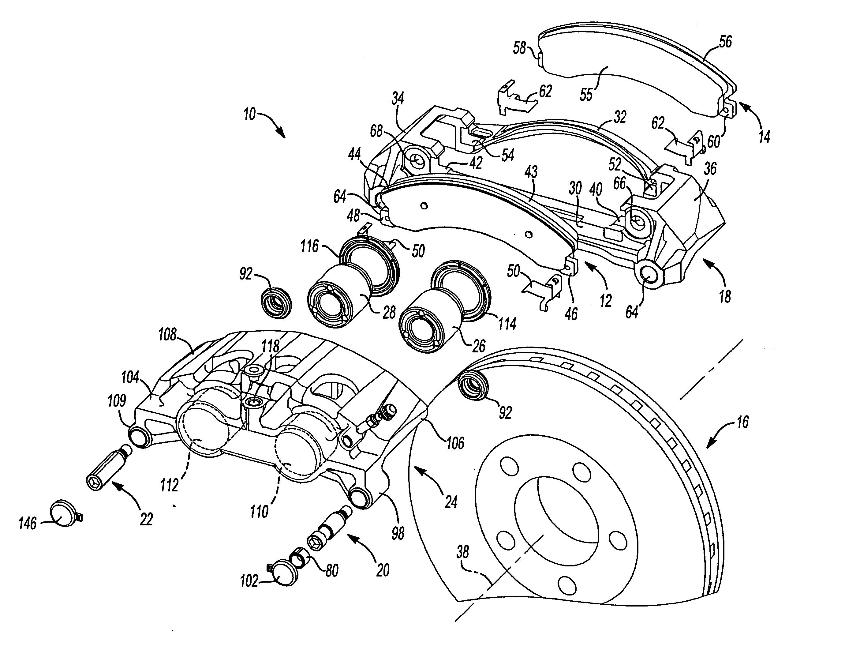
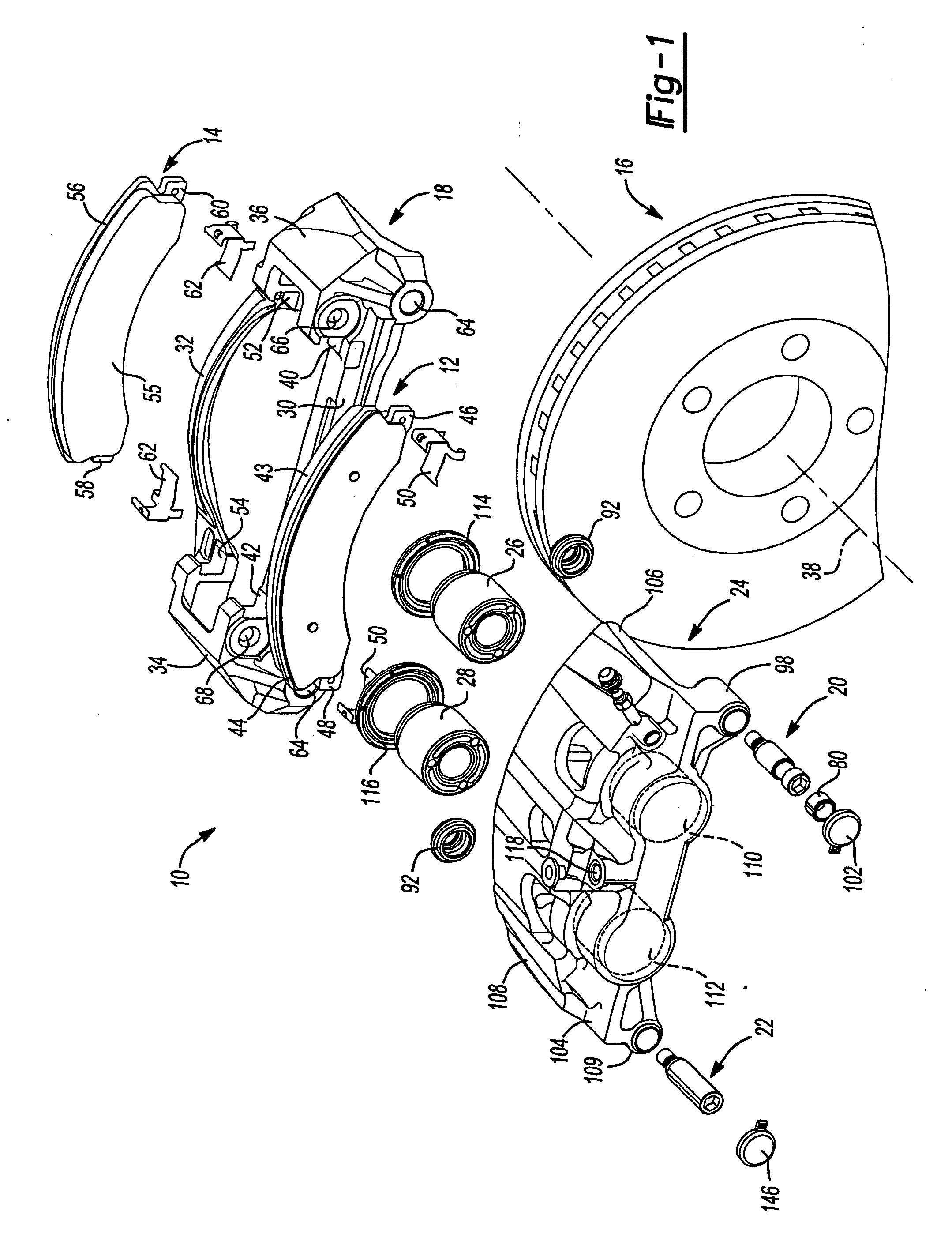
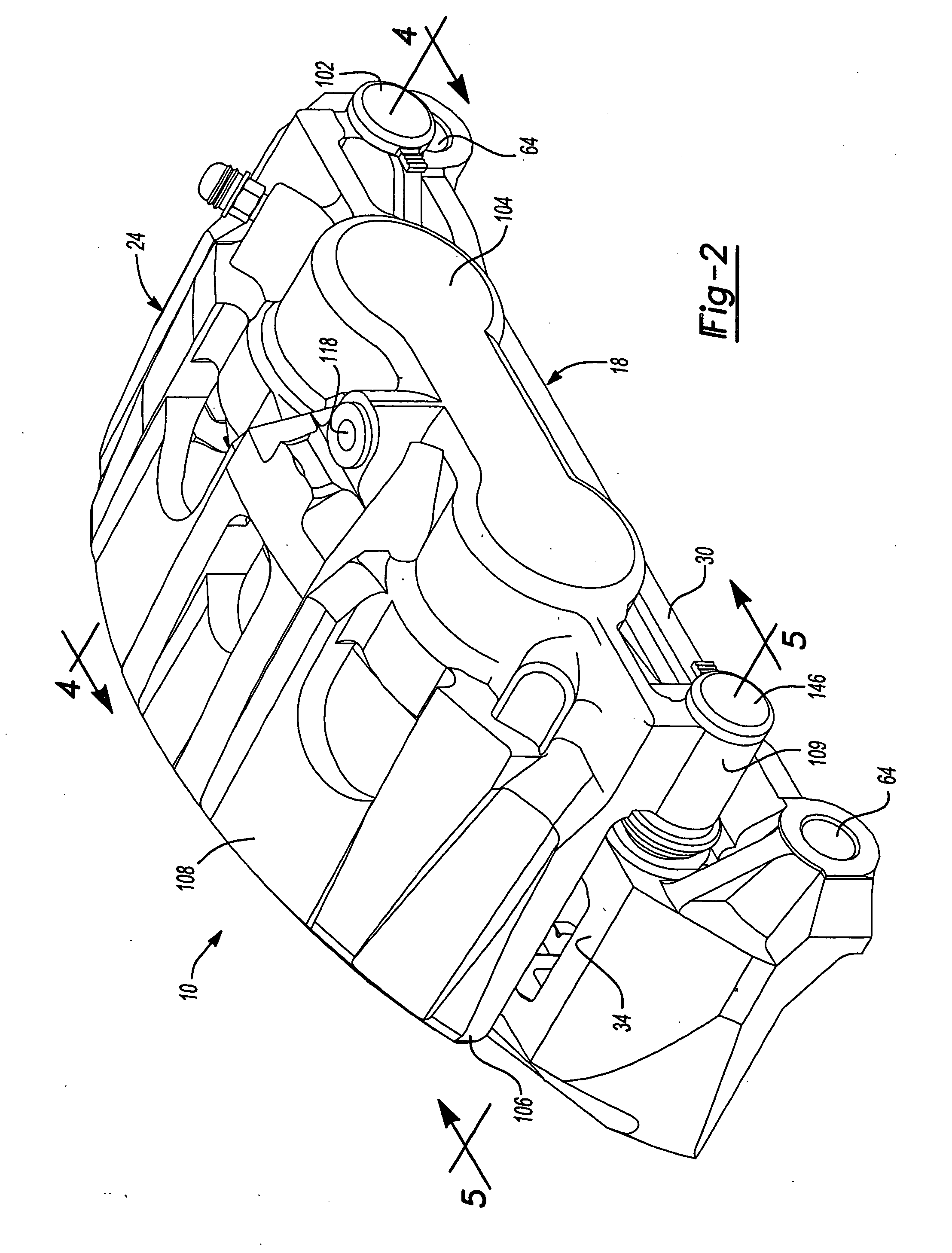
[0015] With reference to FIGS. 1-6, a disc brake constructed in accordance with the teachings of the present invention is identified at reference numeral 10. Disc brake 10 is operable to selectively clamp an inboard brake shoe 12 and an outboard brake shoe 14 against a rotatable disc 16 to decelerate a vehicle (not shown). Disc brake 10 includes a support bracket 18 adapted to mount to a steering knuckle or axle component of the vehicle to support disc brake during operation. A first slide pin 20 and a second slide pin 22 are mounted to support bracket 18 in a manner to resist vibratory loosening as will be described in greater detail hereinafter. First slide pin 20 and second slide pin 22 laterally inwardly protrude from support bracket 18. A caliper 24 is slidably supported on first slide pin 20 and second slide p...


PUM


Abstract

The present invention relates to a disc brake operable to apply a clamping force to a rotatable disc. The disc brake includes a support bracket, slide pins coupled to the support bracket, inner and outer brake shoes and a caliper supported by the slide pins. The support bracket is a substantially rectangular frame defining a window. The window is adapted to accept a portion of a disc protruding therethrough. The support bracket includes a pair of spaced apart apertures extending through the frame where each aperture includes a threaded portion and a conical seat extending along an axis aligned to intersect the disc. The slide pins are threadingly engaged with a threaded portion. The slide pins do not extend through the window but protrude outwardly away from the window. Each slide pin has a tapered portion in engagement with one of the conical seats.

Description

BACKGROUND AND SUMMARY OF THE INVENTION [0001] The present invention relates to a disc brake and, more particularly, to a disc brake caliper slide pin having a tapered design. [0002] Automotive components are typically exposed to a wide variety of environmental inputs including variations in temperature and load throughout operation of a vehicle. Use of a vehicle over rough surfaces provides a road load vibrational input as well. To assure proper operation of a vehicle component, it is desirable to maintain the structural integrity of the component or assembly for an extended time period. [0003] Brake assemblies typically include a number of components interconnected to one another via threaded fasteners. To assure proper braking operation, it is desirable that the thread fasteners maintain a desired clamp load during and after exposure to the environmental and operational inputs previously discussed. Some bolted joints have experienced reduced clamp load or “backing-off” for a numb...

Claims


Application Information

Patent Timeline
Patent Type & Authority Applications(United States)
IPC IPC(8): F16D65/14F16D65/18
CPCF16D55/227
Inventor BARBOSA, MANUELBARRETT, SEANJEDELE, PHILIP
Owner AKEBONO CORP (NORTH AMERICA)
Why Eureka
Try Eureka