Knit zippers
A technology for knitted zippers and zippers, applied in the field of knitted zippers, can solve problems such as yarn wear and tear, zipper tape separation, etc., and achieve the effect of increasing tension
- Summary
- Abstract
- Description
- Claims
- Application Information
AI Technical Summary
Problems solved by technology
Method used
Image
Examples
no. 1 example
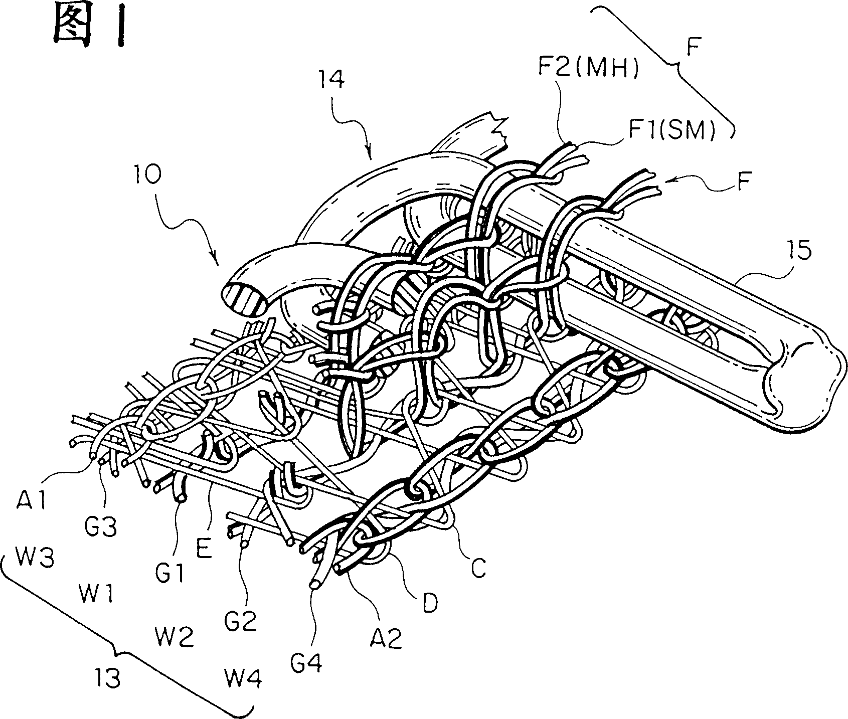
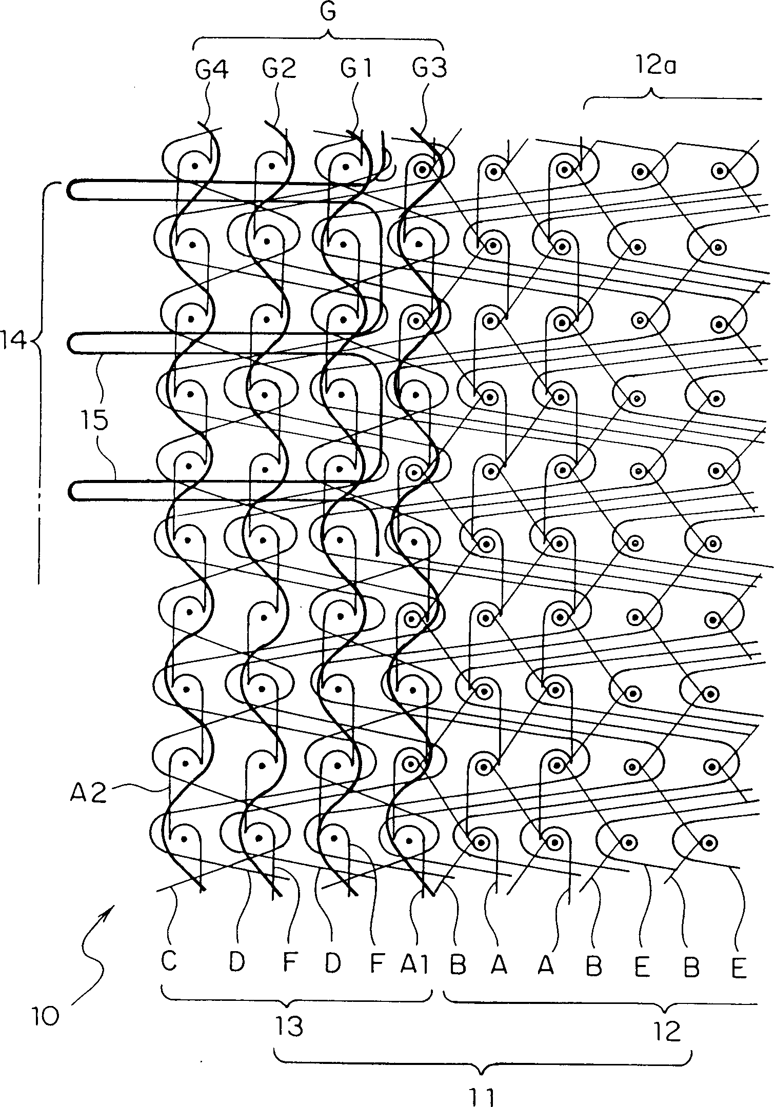
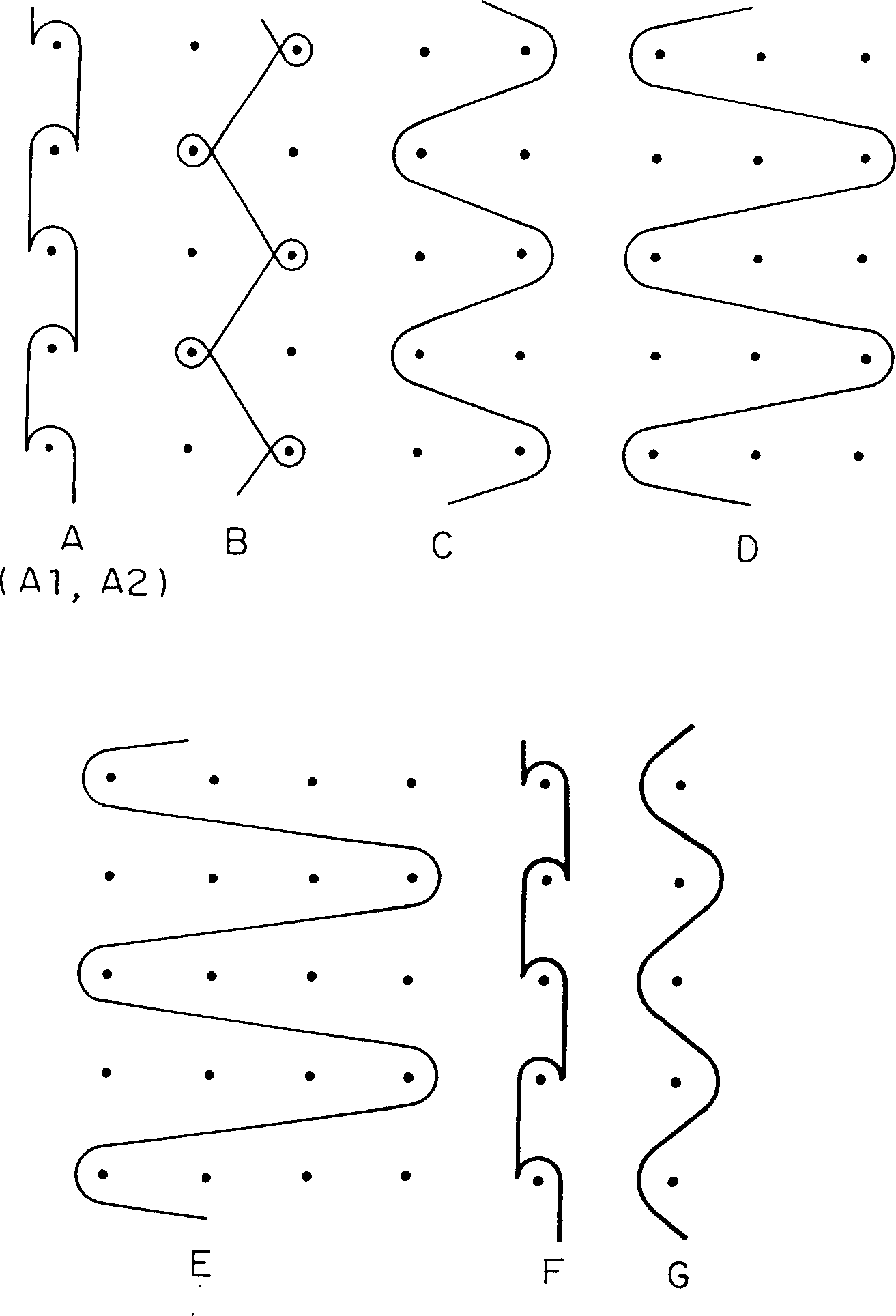
[0032] Hereinafter, preferred embodiments of the present invention will be specifically described based on examples shown in the drawings. Figures 1-3 show a first embodiment of the invention, and Figure 1 is a front perspective view of a portion of a knitted zipper, schematically showing the installation of a continuous row of zipper elements. figure 2 is the entire warp structure diagram representing the same zipper with its omitted part, and image 3 is the warp knitting structure diagram of each knitting yarn in the same knitting zipper.
[0033] Meanwhile, although FIG. 1 shows a situation in which the zipper element mounting part is shown as the center of the figure, and the main part of the zipper tape is omitted and each knitting yarn is loose for easy understanding, it can be understood that the actual knitting pattern and each knitting yarn The coiled part is tightly pulled tightly. In addition, although knitting yarns having various sizes are shown in the same fig...
no. 2 example
[0058] FIG. 6 shows a second embodiment of the present invention, and its zipper stringer 10 has the same knitting structure as that of the first embodiment. However, according to this embodiment, the fixed chain knitting yarn (F) is not composed of composite fiber yarn but ordinary synthetic fiber material. And the warp-lining yarns (G1-G4) of all the zipper element mounting portions 13 are composite fiber yarns composed of heat-shrinkable fiber material (SM) and heat-melt fiber material (MM). According to this embodiment, the fixed chain knitting yarn (F) may also consist of the same composite fiber yarn as the warp laying yarns (G1-G4), as in the first embodiment. This function is substantially the same as that of the first embodiment.
no. 3 example
[0060] Figure 7 A third embodiment of the present invention is shown, and the knitting structure of its zipper stringer 10 is the same as that of the first embodiment. However, also according to this embodiment, the fixed chain knitting yarn (F) is composed of ordinary fiber yarns, and the weft insertion yarns (C) and (D) which are constituent yarns of the fastener element mounting portion 13 are composed of the composite fiber yarns of the present invention. Composition, which consists of heat-shrinkable fiber material (SM) and heat-melt fiber material (MM). According to this embodiment, the fixed chain knitting yarn (F) may also consist of the same composite fiber yarn as in the first embodiment, and in this case, the composite fiber yarn may be the same as the weft inserted yarn (C) and ( D) Same material. Its function is substantially the same as that of the first and second embodiments.
[0061] Furthermore, all the fixed chain knitting yarns (F), warp-lining yarns (G...
PUM
 Abstract
Description
Claims
Application Information
 - R&D
- Intellectual Property
- Life Sciences
- Materials
- Tech Scout
- Unparalleled Data Quality
- Higher Quality Content
- 60% Fewer Hallucinations
Browse by: Latest US Patents, China's latest patents, Technical Efficacy Thesaurus, Application Domain, Technology Topic, Popular Technical Reports.
© 2025 PatSnap. All rights reserved.Legal|Privacy policy|Modern Slavery Act Transparency Statement|Sitemap|About US| Contact US: help@patsnap.com


