Beverage Container With Integral Flow Control Member Having Vent And Outlet Pinhole Membranes And Safety Button

a beverage container and flow control technology, applied in the field of fluid flow control devices for beverage containers, can solve the problems of reducing the resilient force needed to close the slit flap, slits and/or becoming obstructed, so as to reduce the fluid pressure, and limit the fluid pressure

Inactive Publication Date: 2007-03-08
MEDELA HLDG AG
View PDF31 Cites 70 Cited by
  • Summary
  • Abstract
  • Description
  • Claims
  • Application Information

AI Technical Summary

Benefits of technology

[0011] In accordance with a first aspect of the present invention, the spout assembly includes a spout structure that utilizes a baffle disposed in a tube-like spout wall to minimize liquid pressure on an outlet membrane mounted over an end of the spout wall. The tube-like spout wall defines a flow channel extending from the upper wall of the cap to a spout opening, and the baffle, which is integrally formed on an inside surface of the spout wall. The baffle includes a wall that is substantially perpendicular to the flow channel, and defines a relatively small opening (in comparison to a width of the flow channel) between a beverage storage chamber and the outlet membrane. The baffle functions to limit fluid pressure in the region between the baffle and the outlet membrane (i.e., in the presence of a higher fluid pressure downstream of the baffle), thereby reducing fluid pressure on the outlet membrane, and thus reducing the chance of leakage through the outlet membrane. In one embodiment, the upper portion of the spout wall is flexible to facilitate flow through the outlet membrane.
[0012] In one embodiment, the outlet membrane is formed from a suitable elastomeric material (e.g., soft rubber, thermoplastic elastomer, or silicone) that is punctured to form multiple, substantially round pinholes that remain closed to prevent fluid flow through the membrane and flow channel under normal atmospheric conditions (i.e., while the membrane remains non-deformed), thereby providing a desired “no drip” characteristic. Conversely, when subjected to such an applied pressure differential (e.g., when sucked on by a child), the membrane stretches (deforms), thereby causing some or all of the pinholes to open and to facilitate fluid flow rate through the membrane, which is substantially unimpeded by the baffle under these conditions. Because the amount that the pinholes open, and the associated fluid flow through the pinholes, is related to the applied pressure differential, the present invention provides a flow control structure that automatically adjusts its fluid flow rate to the applied suction. In addition, because the pinholes are substantially round, the pinholes resist the clogging and tearing problems associated with slit-type flow control structures.
[0014] According to another aspect of the invention, the beverage container includes a vent mechanism including a vent opening that is defined, for example, in the upper wall of the cap adjacent to the spout assembly, and a vent (second) membrane that is disposed over the vent opening. Similar to the outlet membrane mounted over the spout, the vent membrane includes normally-closed pinholes that open in response to an applied pressure differential (i.e., a vacuum condition inside the cup caused by liquid being drawn through the spout), thereby allowing air to pass through the vent membrane and vent opening into the cup. The vent membrane closes when a user finishes drinking and the pinholes close, so beverage that may be located between the vent opening and the vent membrane is prevented from passing through the vent membrane, thus avoiding the dripping problem associated with conventional non-spill beverage containers. To facilitate deformation of the vent membrane (e.g., toward the cap to facilitate the venting process), the vent membrane is spaced from (e.g., supported over) the upper wall of the cap such that an air gap is present between the vent opening and the vent membrane. In one embodiment, the vent opening is disposed in a bowl-shaped depression that is integrally molded with the upper wall of the cap, and disposed below a round vent membrane, thus providing a bowl-shaped clearance for deformation of the round vent membrane to facilitate air flow into the container.

Problems solved by technology

One problem associated with conventional non-spill cups is that the elastomeric material used to form the slit-type “no drip” flow control valves can fatigue in the region of the slits and / or become obstructed over time, and the resulting loss of resilience can cause leakage when the slit flaps fail to fully close after use.
This failure of the slit flaps to close can be caused by any of several mechanisms, or a combination thereof.
First, repeated shearing forces exerted at the end of each slit due to repeated use can cause tearing of the elastomeric material in this region, thereby reducing the resilient forces needed to close the slit flaps after use.
Second, thermal cycling or mechanical cleaning (brushing) of the elastomeric material due, for example, to repeated washing, can cause the elastomeric material to become less elastic (i.e., more brittle), which can also reduce the resilience of the slit flaps.
Third, solid deposits left by liquids passing through the slits can accumulate over time to impede the slit flaps from closing fully.
A second problem associated with conventional non-spill cups is that the “no drip” flow control valves are typically located inside the short, straw-like drinking spout such that a small, open upper section of the spout is located above the valve.
Another problem associated with conventional beverage containers is that vents are required to allow air into the cup as liquid is drawn out to prevent a vacuum condition inside the beverage chamber.
Conventional non-spill cups typically utilize elastomeric vent devices having slits that function in a manner similar to the conventional flow control valve used in the drinking spouts, and thus are subject to clogging and tearing problems similar to those described above with respect to the drinking spout valve.
An additional problem associated with child sippy cups is a safety requirement that no small part of the sippy cup can be easily removed and ingested by a child, and thus pose a potential choke-type hazard.
This alternative embodiment would reduce dripping through the slit-like opening due to the pressure reducing function of the baffle, but would be subject to the problems described above.
In addition, the safety button is secured to the socket such that the safety button can only be easily disconnected from the cap by pushing the safety button through the socket from the underside surface of the cap, thereby meeting the safety requirement requiring that the cap be removed from the container body before the flow control member can be removed from the cap.

Method used


Image

  • Beverage Container With Integral Flow Control Member Having Vent And Outlet Pinhole Membranes And Safety Button
  • Beverage Container With Integral Flow Control Member Having Vent And Outlet Pinhole Membranes And Safety Button
  • Beverage Container With Integral Flow Control Member Having Vent And Outlet Pinhole Membranes And Safety Button

Examples


Embodiment Construction

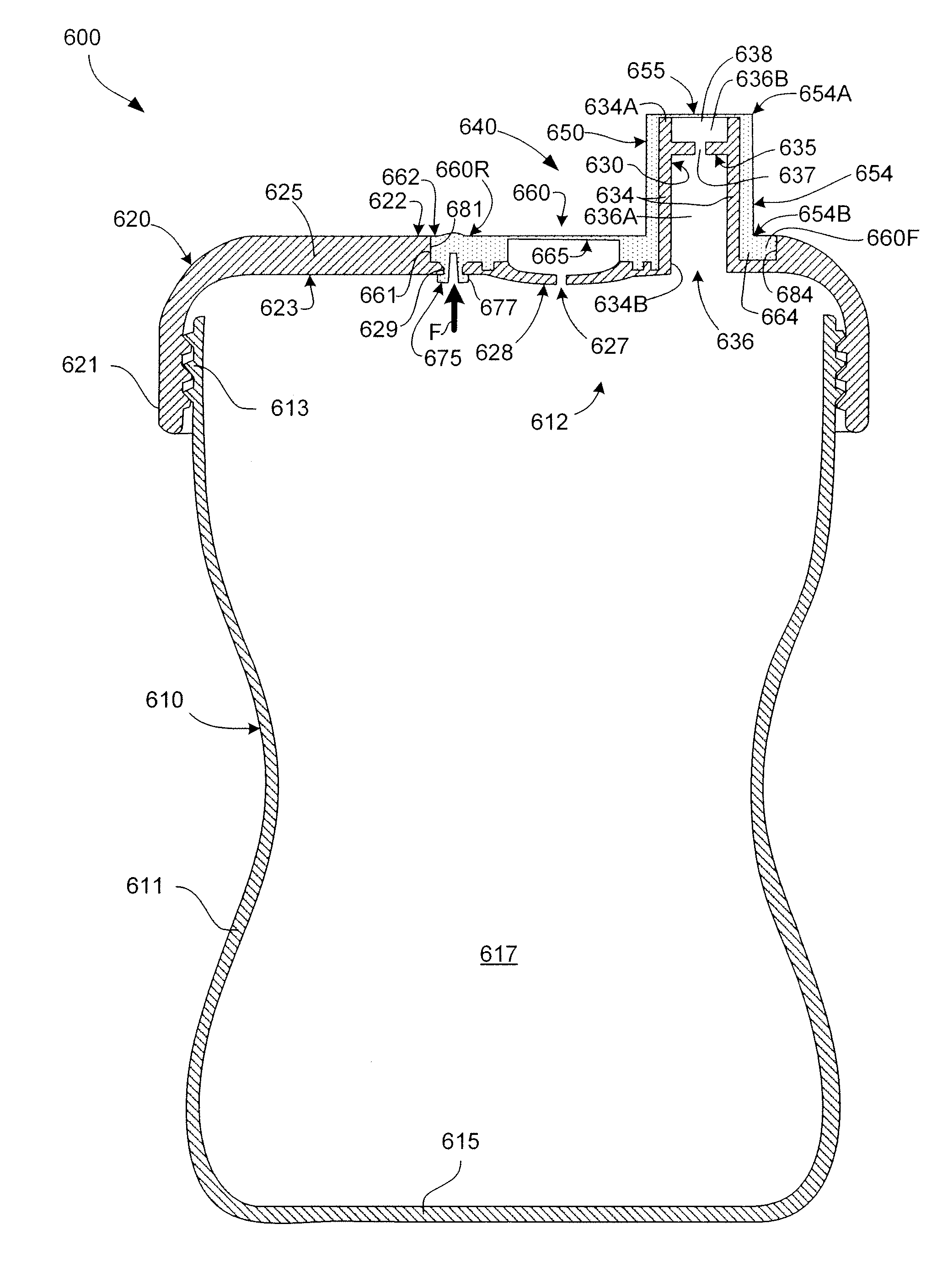
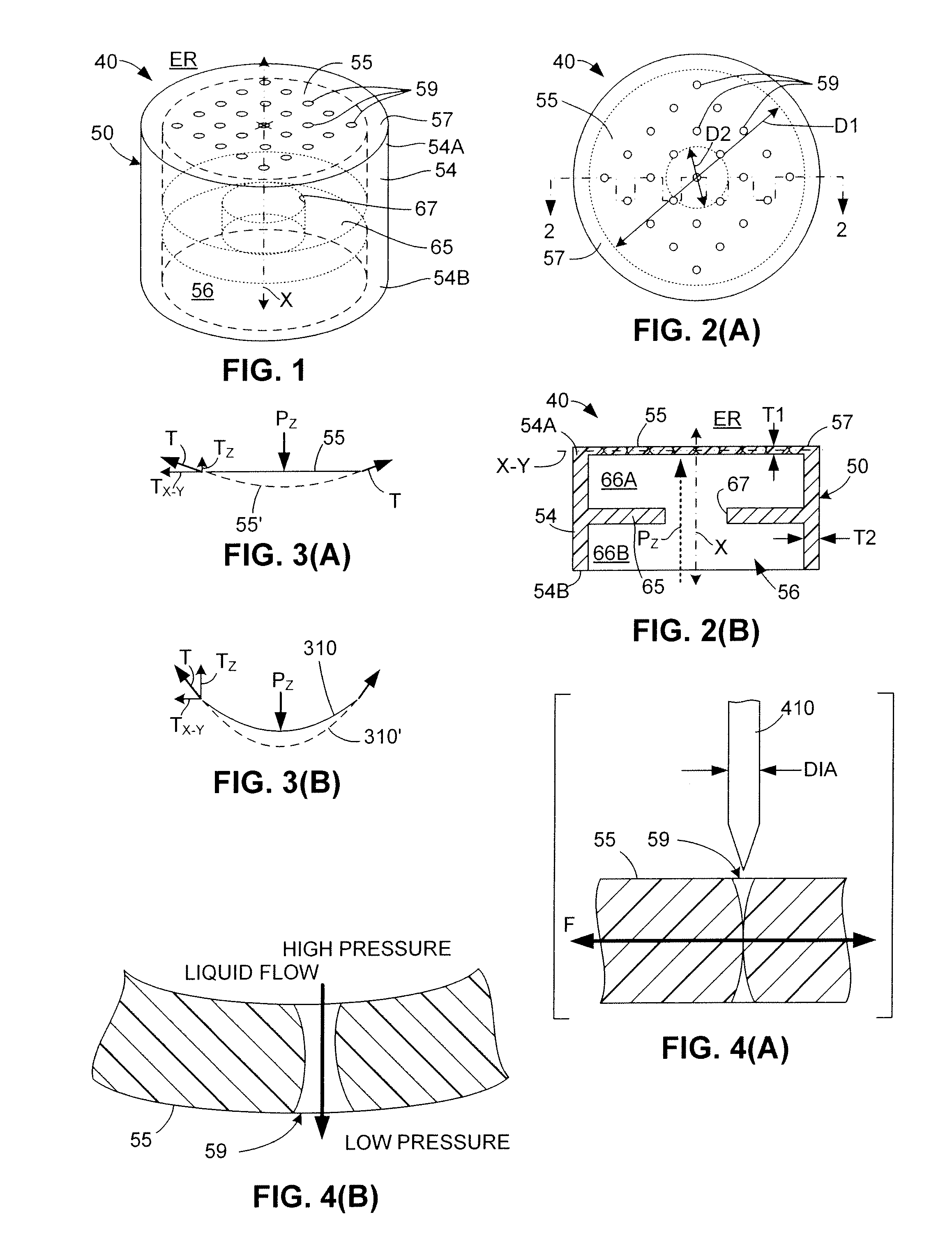
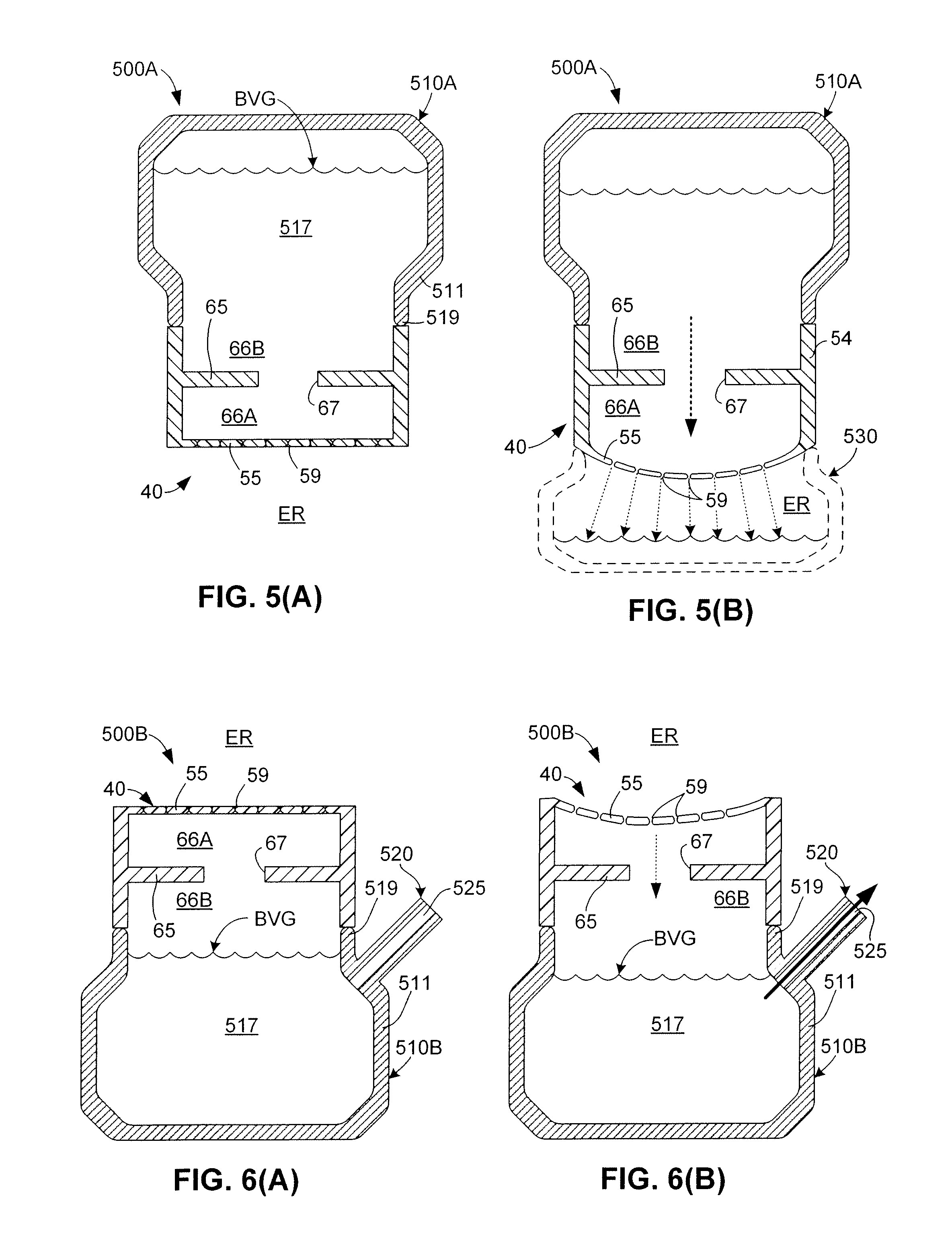
[0029] The present invention relates to an improved flow control member for a beverage container. The following description is presented to enable one of ordinary skill in the art to make and use the invention as provided in the context of a particular application and its requirements. As used herein, directional terms such as “upper”, “upwards”, “lower”, “downward”, “front”, “rear”, are intended to provide relative positions for purposes of description, and are not intended to designate an absolute frame of reference. In addition, the phrases “integrally connected” and “integrally molded” is used herein to describe the connective relationship between two portions of a single molded or machined structure, and are distinguished from the terms “connected”, or “coupled” (without the modifier “integrally”), which indicates two separate structures that are joined by way of, for example, adhesive, fastener, clip, threaded screw or movable joint. Various modifications to the preferred embo...


PUM


Abstract

A non-spill beverage container includes a cap having a tube-like spout and a baffle mounted inside the spout, and a flow control member having a spout (first) membrane supported over the spout opening. A vent (second) membrane that is disposed adjacent to the spout and is supported over a vent opening defined in the cap. The spout and vent membranes are punctured to form multiple, substantially round pinholes that remain closed to prevent fluid flow under normal atmospheric conditions, and open to facilitate fluid flow under an applied pressure differential (e.g., when sucked on by a child). The baffle limits the differential pressure applied to the spout membrane when the container is not in use. The flow control member can only be removed from the cap by removing the cap from the container body and pressing a flexible safety button from an inside surface of the cap.

Description

RELATED APPLICATIONS [0001] This application is a continuation-in-part of U.S. Patent application for “NON-SPILL CONTAINER WITH FLOW CONTROL STRUCTURE INCLUDING BAFFLE AND ELASTIC MEMBRANE HAVING NORMALLY-CLOSED PINHOLES”, U.S. application Ser. No. 11 / 131,721, filed May 17, 2005.FIELD OF THE INVENTION [0002] The present invention relates to fluid flow control devices for beverage containers, and more specifically it relates to elastic flow control members for, e.g., child sippy cups, and adult “travel” mugs and sports bottles. RELATED ART [0003] Sippy cups, travel mugs and sports bottles represent three types of beverage containers that utilize flow control devices to control the ingestion of beverage in response to an applied sucking force. Sippy cups are a type of spill-resistant container typically made for children that include a cup body and a screw-on or snap-on lid having a drinking spout molded thereon. An inexpensive flow control element, such as a soft rubber or silicone o...

Claims


Application Information

Patent Timeline
Patent Type & Authority Applications(United States)
IPC IPC(8): B65D51/16A47G19/22
CPCA47G19/2272
Inventor HOLLEY, JAMES W. JR.
Owner MEDELA HLDG AG
Why Eureka
Try Eureka