Quick release bicycle wheel

Inactive Publication Date: 2007-03-08
DAVID MONTAGUE
22 Cites 24 Cited by

AI-Extracted Technical Summary

Problems solved by technology

The single process of opening the quick release cam does not produce enough “throw” to allow the quick release and the nut to clear the recess or tabs to exit from the dropout.
However, when the wheel is re-inserted into the dropouts, the adjusting nut remains unscrewed and the wheel, while looking like it is attached to the bicycle or other wheeled vehicle, is not.
In this “dangerous state” condition the bicycle is extremely dangerous as it appears to be rideable, but the front wheel can easily separate from the wheel fork.
In addition, in order to do this, the rider must hold the bicycle up with one hand, hold the quick release on one side of the bicycle with another hand, and turn the adjusting nut on the opposite side of the bicycle with yet another hand—making the process of safely fastening a wheel difficult at best for the average rider with only two hands.
Furthermore, the process of adjusting the nut to the correct ...

Benefits of technology

[0016] The objective of the present invention is to provide a wheel release system that is fool-proof, safe, and easy and intuitive to use by the inexperienced rider with no instructions. In addition, the system must be light weight, simple, and inexpensive to manufacture. This objective is achieved in a system wherein the wheel can be easily removed by a manual operation on one side of the wheel but is prevented from unexpected separation at all times while engaged with the wheel. A laterally moving skewer mounted concentrically inside a hollow axle is equipped with a “non-touch” nut on one end and is spring loaded toward a quick release cam on t...

Abstract

The present invention relates to a wheel quick release system for a bicycle or other wheeled vehicle where the wheel can be easily removed by a manual operation on only one side of the wheel hub but is prevented from unexpected separation at all times while engaged with the wheel. A laterally moving skewer mounted concentrically inside a hollow axle is equipped with a “non-touch” nut on one end and is spring loaded toward a quick release cam on the other end thereby always urging the nut against the adjacent dropout. In order to remove the wheel, the quick release cam is operated and the quick release side assembly is pushed axially inward and a safety mechanism is operated and held in this position while the wheel is removed from the fork dropouts. When the wheel is again inserted into the wheel fork, the skewer automatically locks onto the dropouts, and subsequently if the quick release cam is inadvertently left open by the user, the wheel will be somewhat loose but will remain safely inserted in the wheel mounts. In this way, if the bicycle or wheeled vehicle looks safe to ride, it is safe to ride.

Application Domain

HubsAxle suspensions +3

Technology Topic

Hand maneuverEngineering +1

Image

  • Quick release bicycle wheel
  • Quick release bicycle wheel
  • Quick release bicycle wheel

Examples

  • Experimental program(1)

Example

[0073] The following is a detailed description of the preferred embodiments of the present invention. It is apparent to those skilled in the art that any number of modifications can be made to the present invention and any such modification shall fall within the present invention even if not specifically shown.
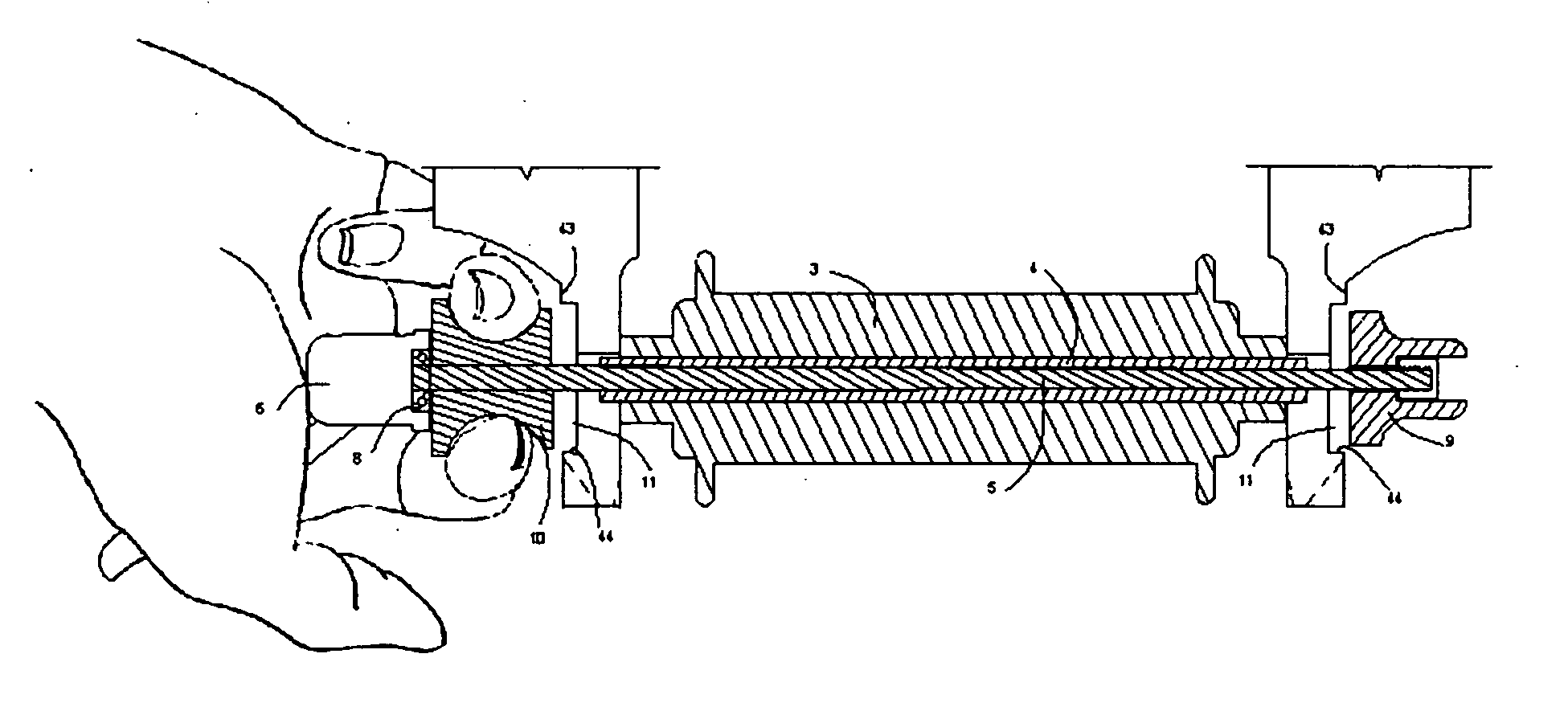
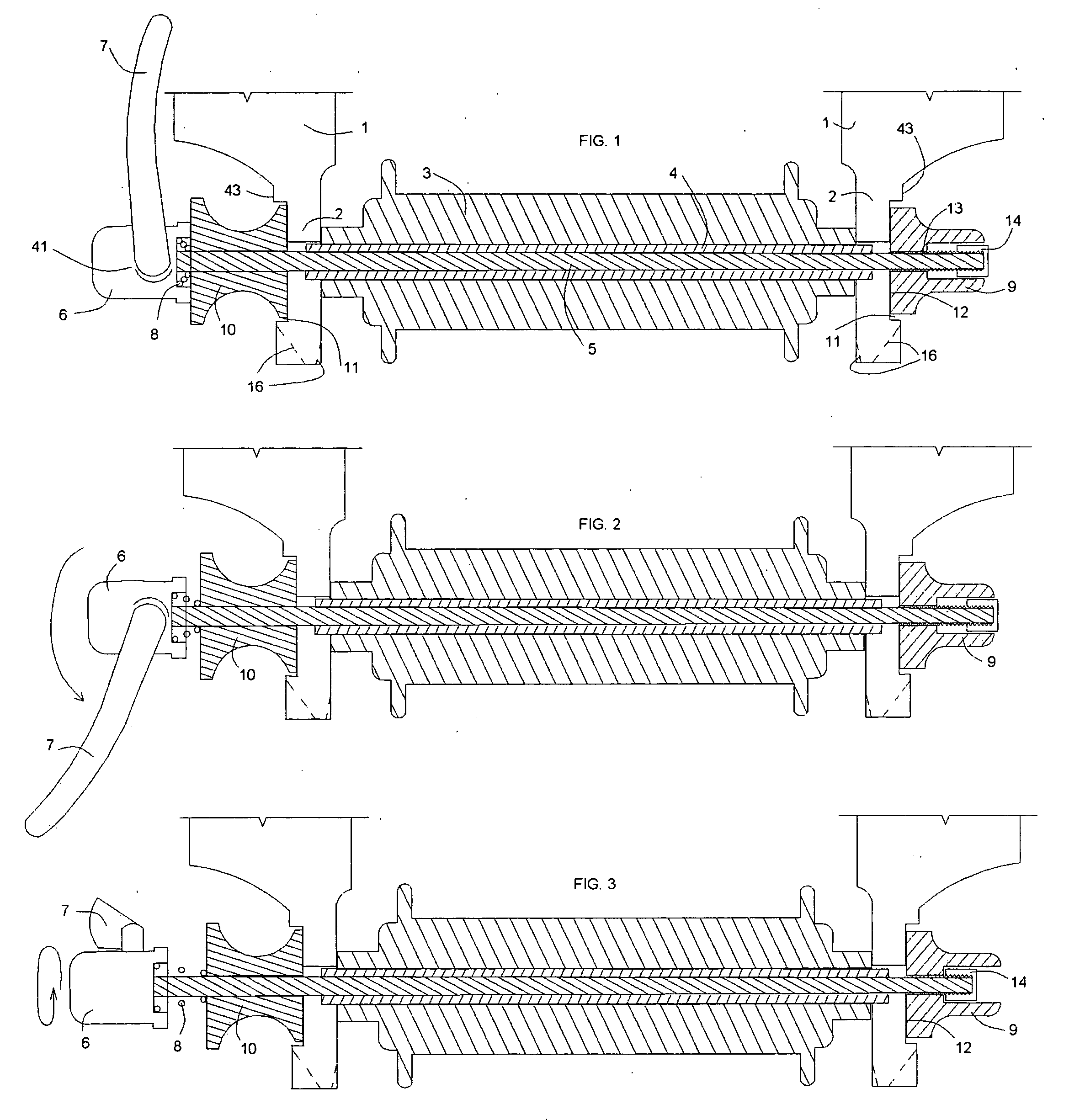
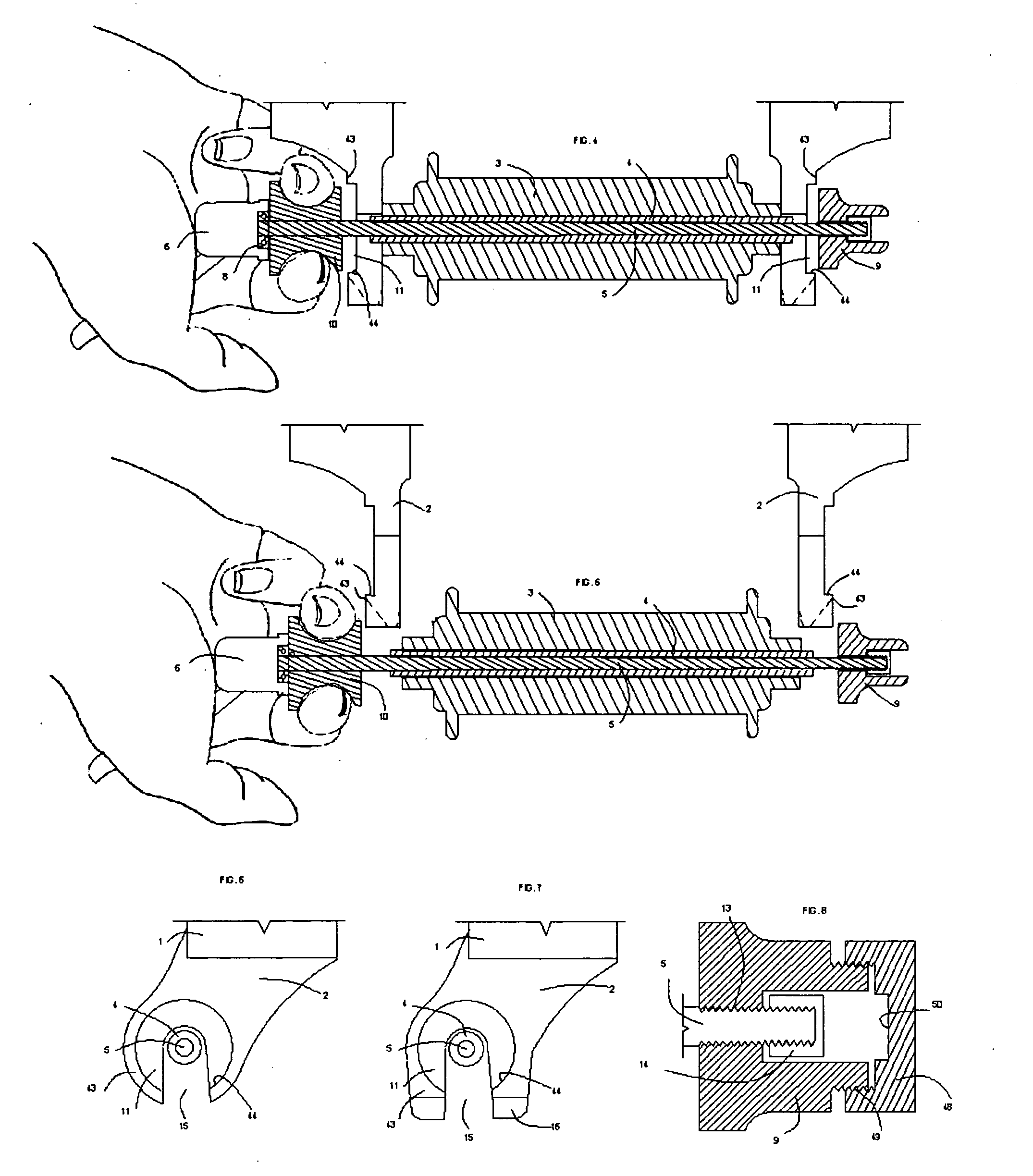
[0074] The fundamental underlying principle of the present invention comprises a wheel fork or vehicle frame with two wheel mounts, or dropouts, where each of the dropouts has a recessed surface or retaining tabs, either on its outer face, or its inner face, or both. The quick release wheel has a hollow axle hub and an interior mounted skewer, wherein said skewer has a quick release cam or other fastening device on one end and a nut on the other end and is spring loaded toward the quick release end such that the nut is always urged against and into the adjacent dropout recessed surface to prevent its rotation and exit from the recess. On the quick release end of the skewer, a safety device of some form is also urged by spring into a recess. In this way, neither end is able to exit the dropout unless the quick release end is pushed inward axially allowing the nut to exit its recess area. In some cases, the safety device located on the quick release end of the skewer must be operated separately from the nut, and in some cases, the safety device can be operated in the same motion as the device to allow the wheel to be removed from the dropouts.
[0075]FIGS. 1 through 8 show the first preferred embodiment where a quick release lever is unlocked and spun, then it is pushed inward while a safety pull cylinder is pulled outward allowing the wheel to be removed. Referring to FIG. 1, a fork 1 with dropouts 2 holds a standard hub 3, with a hollow axle 4 housing a skewer 5 which has mounted on one end a standard quick release 6 and a standard quick release lever 7 with a standard quick release spring 8, and an adjusting nut 9. This adjusting nut 9 is a “non-touch” nut which, unlike conventional systems, does not require the operator to touch or hold it while spinning the quick release on the opposite end.
[0076] On the quick release end of the skewer 5, a novel safety pull cylinder 10, which could take a wide variety of “pullable” round, and non-round configurations, is axially mounted and urged into a dropout recess 11 by the quick release spring 8 which also presses the adjusting nut knarled surface 12 against the opposite dropout recess 11. The combination of the pressure from quick release spring 8 and the adjusting nut knarled surface 12 holds the adjusting nut 9 from spinning relative to dropout 2 when the quick release 6 is spun in order to unscrew the adjusting nut 9 on the skewer threaded area 13. This, unlike the prior art, permits the one sided operation of the present invention. The adjusting nut retaining cap 14 ensures that the adjusting nut 9 does not unscrew off the end of skewer 5. When adjusting nut 9 is unscrewed to a point where it meets adjusting nut retaining cap 14, which freely enters a cavity in the side of adjusting nut 9, it can no longer unscrew and begins to spin with skewer 5, and adjusting nut knurled surface 12 begins to spin relative to dropout recess 11 and dropout 2 and often produces an audible grinding noise and/or a different spinning feeling in quick release 6 indicating to the user that skewer 5 has been sufficiently rotated and no further spinning of skewer 5 is necessary for wheel removal.
[0077]FIG. 2 illustrates the unlocking operation of the quick release cam 41. In many cases, this does not offer enough separation between the adjusting nut 9 and the quick release 6, and, if a wide throw quick release is not used, the subsequent rotation of the quick release 6, as shown in FIG. 3, is required in order to further spread the distance between the adjusting nut 9 and the quick release 6 in order to remove the wheel. Rotation of quick release 6 causes spreading until adjusting nut 9 encounters adjusting nut retaining cap 14 or another stopping surface of some kind.
[0078]FIG. 4 shows the next step in the wheel removal process where quick release 6 is pushed axially inward while the safety pull cylinder is squeezed against it thus causing the safety pull cylinder 10 to exit the dropout recess 11 and clear dropout restraining surface 44 while the adjusting nut 9 also exits the corresponding dropout recess 11 and also clears dropout restraining surface 44. Dropout restraining surface 44 plays a critical role in preventing the wheel hub assembly from unexpected separation from the fork. Again, dropout restraining surface 44 and dropout raised surface 43 could be on a “tab” rather than the recess side as shown. FIG. 5 is the last of the sequence and shows the skewer 5 having exited through dropout opening 15 and the safety pull cylinder 10 and the adjusting nut 9 having bypassed the dropout raised surface 43. The embodiment can be used with variety of different dropout configurations. FIG. 6 shows a conventional dropout 2, which can be used where dropout restraining surface 44 is positioned at the lower area of dropout recess 11.
[0079]FIG. 7 shows a novel dropout wherein dropout ramps 16 are added on the lower sides of the dropout 2 and where the tip of the dropout is set in a position which optimizes the ease of insertion of the wheel hub into the dropout while being “blunt” enough to avoid being dangerous and avoid poking through a shipping carton. The dropout ramp 16 on the hub/wheel side of the dropout serves to facilitate the centering of the hub as it enters the dropouts. The dropout ramp 16 on the outside non-hub/wheel side of the dropout serves to spread the safety pull cylinder 10 and the adjusting nut 9 apart. The slight angle of the dropout opening 15 also serves to facilitate the centering of the hub as it enters the dropouts as does a taper between opening 15 and dropout ramp 16.
[0080] When re-installing the wheel, the process is done in reverse. However, if a ramp 16 is used, FIG. 5 would not require a hand to squeeze quick release 6 against safety pull cylinder 10 as the ramps perform this function. When the wheel is being re-installed on the fork 1, this dropout ramp 16 automatically forces the adjusting nut 9, and the safety pull cylinder 10 to separate, compressing quick release spring 8, and then moving up and over the dropout raised surface 43 and subsequently being pulled into the dropout recess 11 by quick release spring 8. At this point, even though the quick release 6 and adjusting nut 9 have not been manually operated in any way, the wheel cannot be removed from the fork. On conventional bicycles, when the wheel is re-inserted into the dropouts and would appear to be safe to ride, there is nothing to stop it from again inadvertently separating from the fork. This is the safe condition that the present invention offers over conventional technology. A conventional adjusting nut may be used in conjunction with this invention. However, adjusting nut 9, when used with adjusting nut retaining cap 14 is novel in that it does not allow adjusting nut 9 to inadvertently be unscrewed off the end of skewer 5, a common problem on conventional bicycles.
[0081]FIG. 8 shows adjusting nut 9 modified to include a rotation limit control cap 48 which, when the skewer 5 as shown in FIG. 3 is rotated in a tightening manner to the position shown in FIG. 2, it is blocked from being further tightened by the rotation limit control cap stopping surface 50, which encounters adjusting nut retaining cap 14. In this configuration, the quick release 6 is set for perfect tightening of the quick release cam 41 using the quick release lever 7 as shown in going from FIG. 2 to FIG. 1. Rotation limit control cap 48 is adjusted relative to adjusting nut 9 by using rotation limit control cap threading 49, which can be on the outside or inside of adjusting nut 9, to achieve the precise setting. When adjusting nut retaining cap 14 encounters rotation limit control cap stopping surface 50, adjusting nut 9 begins to spin with skewer 5, and surface adjusting nut knarled surface 12 begins to spin relative to dropout recess 11 and dropout 2 and often produces an audible grinding noise as well as a different spinning feeling in the quick release 6 indicating to the user that skewer 5 has been sufficiently rotated and the quick release lever 7 is ready for closing. This novel rotation control system operates without the user touching the adjusting nut 9 and offers pre-set limits on it range of movement providing perfect quick release function for locking the wheel on one end, and perfect outboard setting for clearing dropout raised surface 43 when removing the wheel on the other end. In this way, it is a “smart-no touch” nut which guides the limits of spinning of skewer 5 when both removing the wheel, as well as when re-installing the wheel for proper quick release cam function.
[0082]FIG. 9 through FIG. 15 illustrate a second preferred embodiment which functions the same as the embodiment shown in FIGS. 1 through 8, except is equipped with a centering mechanism for easier wheel removal. This variation uses a two part safety device instead of the safety pull cylinder 10 shown in FIGS. 1 through 8. FIGS. 9 through 13 illustrate the sequence of removal of the wheel with this embodiment where the safety system allows the inner centering cylinder 18 to always be in contact with dropout 2 while the quick release head 6 is released, rotated, and pushed in thereby centering the mechanism for easier removal. The outer safety pull cylinder 17 must be squeezed simultaneously and opposite to the pushing of quick release head 6 in order for wheel removal. Inner centering cylinder 18 then slides along dropout recess 11 and into dropout recess slide 21 escaping from the wheel dropouts 2 as shown in FIG. 13. Outer safety pull cylinder 17 is too large to fit through dropout recess slide 21 while inner centering cylinder 18 is not. The safety cylinder inner spring 19, held by centering cylinder assembly ring 20, is used to ensure that outer safety pull cylinder 17 remains locked inward and against dropout restraining surface 44.
[0083] When re-installing the wheel, the operation is done in reverse, however, the squeezing shown in FIG. 13 is not required.
[0084] The sequence shown in FIGS. 16 through 19 illustrates a modification of the second preferred embodiment of FIGS. 9 through 15, however, a non-rotatable adjusting nut 46, combined with adjusting nut set screw 30, and a wide throw quick release integral cam arm 22 avoids the need for the spinning of the quick release and skewer as shown in FIG. 11. Surface 23, which rides on quick release cradle 24, varies in distance from the cam center enough such that when quick release integral cam arm 22 goes from FIG. 16 to FIG. 17, it allows non-rotatable adjusting nut 46 to clear dropout restraining surface 44 when skewer 5 is pushed inward axially, as shown in FIG. 18. As in previous figures, outer safety pull 17 must also be squeezed in order to allow for wheel removal as shown in FIG. 19. A standard bicycle nut could be used on this embodiment to replace non-rotatable adjusting nut 46.
[0085] When re-installing the wheel, the operation id done in reverse, however, the squeezing shown in FIG. 19 is not required.
[0086]FIGS. 20 through 27 illustrate a third preferred embodiment which is variation of FIG. 9 where the safety mechanism is operated in the same manner, but functions slightly differently. The slotted outer centering cylinder 25 transfers the quick release 6 pressure onto the dropout raised surface 43, and the inner safety pull cylinder 26 resides in the dropout recess 11, but has two pull areas, or finger holds, extending outside the slotted outer centering cylinder 25 which must be squeezed outward simultaneously to depressing of quick release head 6 for wheel removal. Once again, safety cylinder inner spring 19 ensures that inner safety pull cylinder 26 is always being pushed into dropout recess 11 and quick release spring 8 ensures that adjusting nut 9 is always being pulled into the opposite dropout recess 11 as well. The advantage of this variation over the variation shown in FIG. 9 is that it can use a standard dropout as shown in FIG. 27. When re-installing the wheel, the process is done in reverse.
[0087] All systems shown in FIGS. 1 through 27 require that the user, at a minimum, pushes and squeezes the quick release and safety device together. In some cases, it may be desirable to simply push the quick release with no squeezing action required. FIGS. 28 through 46 show systems where the squeezing action is not required.
[0088]FIGS. 28 through 34 illustrate a fourth preferred embodiment in a system where inner centering cylinder with ring gear 27 is equipped with ring gear 28, and is mounted on ring gear axle 29. As the quick release integral cam arm is opened and pushed, skewer gear teeth 31, force ring gears 28 to rotate, which contacts outer safety cylinder ladder gear 40, attached to outer safety pull cylinder 17, forcing it out of dropout recess 11. In this way, the single action of pushing the quick release integral cam arm 22 and skewer 5 inward causes both the outer safety pull cylinder 17 and non-rotatable adjusting nut 46 to exit dropout recess 11 and allow the wheel to be removed. When re-installing the wheel, the operation is done in reverse, however the pushing arrow shown in FIG. 31 is not needed.
[0089]FIGS. 35 through 40 illustrate a fifth preferred embodiment which uses the same principle of pushing the quick release inward in order to release both sides of the wheel for wheel removal. However, the mechanism of FIGS. 35 through 40 has several unique concepts. The dropout 2 is equipped with dropout inner recess 36 on its inner surface as well as dropout recess 11 on its outer surface. Axle 4 does not extend into the dropout 2 on the quick release side due to a hub safety disc recess 33 which houses a safety disc 34, and a safety disc spring 35. Therefore the load bearing skewer 32 must take the vehicle load when quick release adjustable cam arm 38 is not locked. The quick release adjustable cam arm 38 rotates like previous embodiments, however, when rotated, it does not rotate load bearing skewer 32, but instead causes the adjustable cam 45 to thread up and down skewer adjustable cam threaded area 37 and is restrained from coming off the end by adjustable cam retaining nut 39. Quick release spread disc 42, which could be combined with quick release cradle 24, allows the two to avoid falling into dropout recess 11 which is sized for wheel reversibility. Safety disc 34 and non-rotatable adjusting nut 46 always remain a set distance apart, and when load bearing skewer 32 is pushed, move in unison to both exit their respective recess areas. Safety disc spring 35 and quick release spring 8 ensure that safety disc 34 and non-rotatable adjusting nut 46 remain in recess slots for safety at all times.
[0090]FIGS. 41 through 46 illustrate a sixth preferred embodiment which uses the same principle of pushing the quick release inward in order to release both sides of the wheel for wheel removal. However, unlike all previous preferred embodiments, here the two dropouts 2 are not mirror images of one another and the wheel sides are not reversible. The quick release side dropout 2 has a split dropout safety disc opening 47 which allows safety disc 34, when skewer 5 and adjustable cam 45 are pushed axially inward, to exit dropout inner recess 36 and enter split dropout safety disc opening 47 and clear the dropout for wheel removal. Safety disc 34 and non-rotatable adjusting nut 46 always remain a fixed distance apart. Quick release adjustable cam arm 38 and adjustable cam 45 again, when rotated, do not cause the rotation of skewer 5, but rather thread up and down skewer adjustable cm threaded area 37. The advantage of this embodiment over FIG. 35, is that it uses a standard hub 3, and standard axle 4 diameter.
[0091] All the above variations are interchangeable. Each can be used with a wide throw quick release integral cam arm 22 which can avoid the need for further rotation or spinning after operation of the cam. This allows for the use of a non-rotatable adjusting nut 46 or a conventional bicycle nut. Likewise, all variations can use a small throw quick release 6 which requires further rotation or spinning in order to spread the distance between the quick release and the nut for wheel removal. With the exception of FIGS. 35 through 46, all variations can use the adjusting nut with a rotation limit control cap as shown in FIG. 8 for fast adjustment of quick release arm operation.
[0092] While the present invention has been described by reference to the preferred embodiments using specific words and drawings, it is understood that these descriptions are intended as examples of the present invention, and do not in any way restrict the content of the invention.

PUM

no PUM

Description & Claims & Application Information

We can also present the details of the Description, Claims and Application information to help users get a comprehensive understanding of the technical details of the patent, such as background art, summary of invention, brief description of drawings, description of embodiments, and other original content. On the other hand, users can also determine the specific scope of protection of the technology through the list of claims; as well as understand the changes in the life cycle of the technology with the presentation of the patent timeline. Login to view more.

Similar technology patents

Internally illuminated holiday garland

InactiveUS6739745B1light weight
Owner:VALDES JOANN M

Foundation footing form and accessories

InactiveUS20050023432A1light weighteasily place in position
Owner:HUBER DONALD G +1

Lopper

InactiveUS20090038162A1simplify constructionlight weight
Owner:ARCAS CORP

Bridge Faucet with Side Spray Kit

InactiveUS20100043898A1simple constructionlight weight
Owner:ECKHAUS EFRAIM

Classification and recommendation of technical efficacy words

  • light weight
  • inexpensive to manufacture

Light Emitting Diode Packages

ActiveUS20070247847A1light weight
Owner:CREELED INC

Non-encroaching aircraft passenger seat

Owner:BE AEROSPACE INCORPORATED

Compression support sleeve

InactiveUS7025738B2reduce migrationlight weight
Owner:L&R USA INC

Disposable transducer seal

ActiveUS20050154313A1inexpensive to manufacturequickly and easily instal
Owner:SOLTA MEDICAL

Low cost safety lancet

ActiveUS20070185515A1inexpensive to manufactureeasily assemble together
Owner:FACET TECH LLC

Passive Entry System for Automotive Vehicle Doors

ActiveUS20090160211A1durable in constructioninexpensive to manufacture
Owner:FORD GLOBAL TECH LLC

Fiber optic cables and assemblies for fiber toward the subscriber applications

ActiveUS20110229098A1small cross sectioninexpensive to manufacture
Owner:CORNING OPTICAL COMM LLC
Why Eureka
Try Eureka