
Display device

a technology of a display device and a screen, which is applied in the manufacture of electrode systems, tubes with screens, electric discharge tubes/lamps, etc., can solve the problems of no useful solution for lowering the anode voltage and the anode field, and achieve the effect of reducing the influence of the anode on the emitter

Inactive Publication Date: 2007-03-08
KONINKLIJKE PHILIPS ELECTRONICS NV +1
View PDF7 Cites 1 Cited by
  • Summary
  • Abstract
  • Description
  • Claims
  • Application Information

AI Technical Summary

Benefits of technology

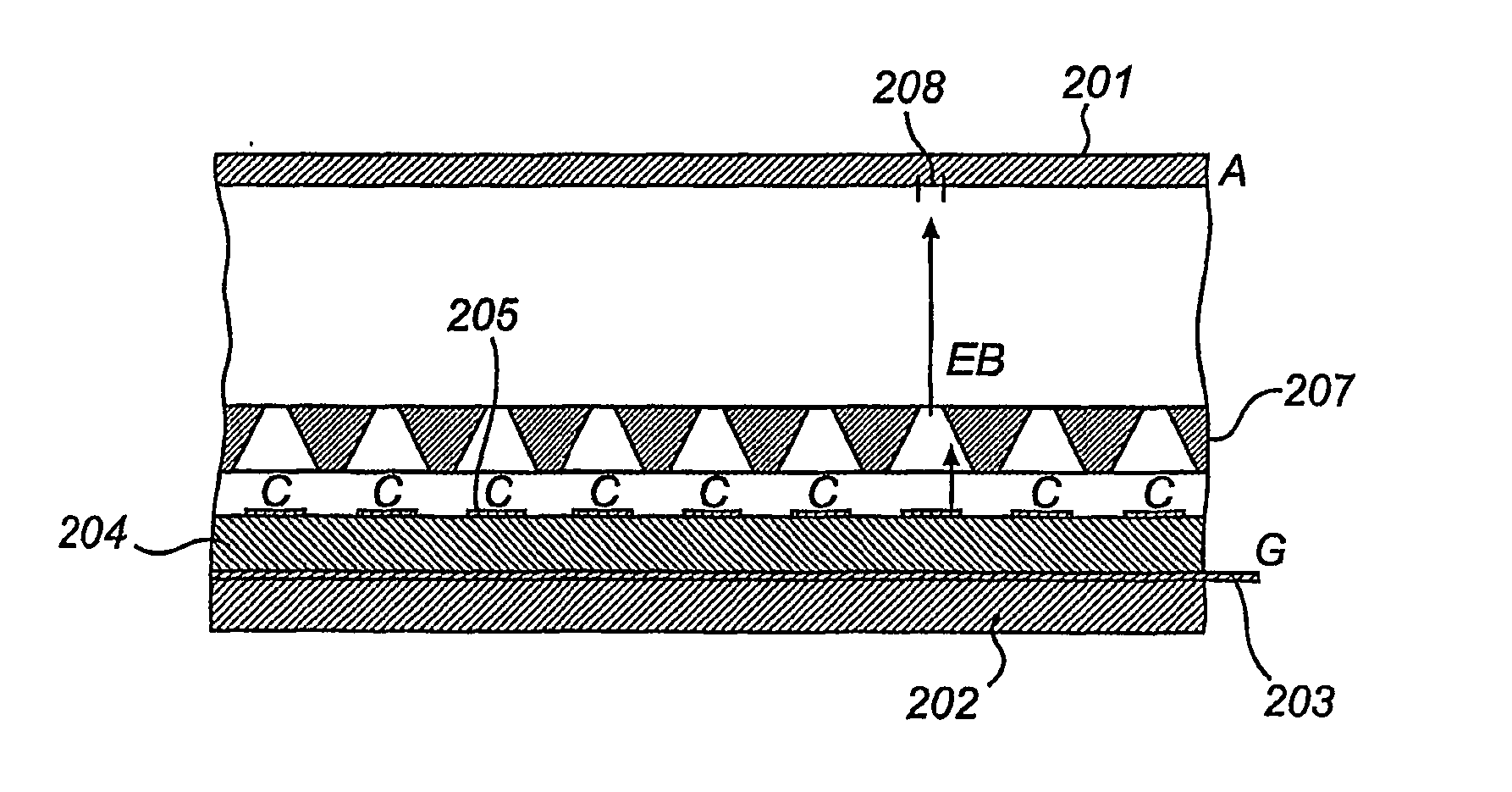
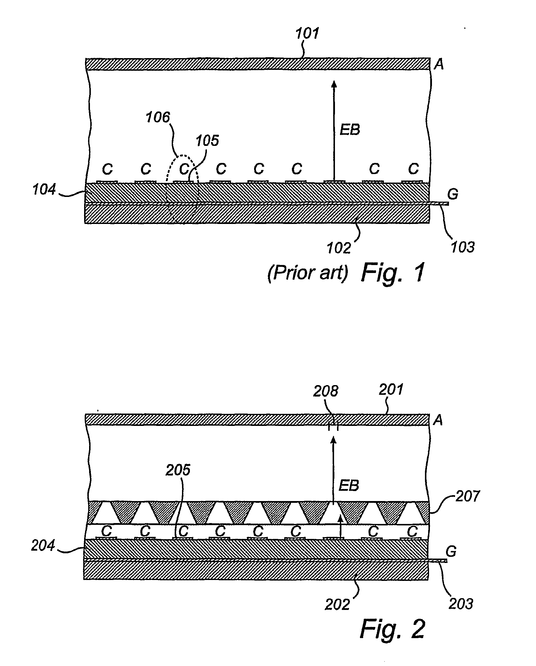
[0005] Such an electron beam guidance element substantially protects the emitter element from the influence of the anode voltage. Thus a low gate electrode voltage may be used, without lowering the anode voltage of the display device.
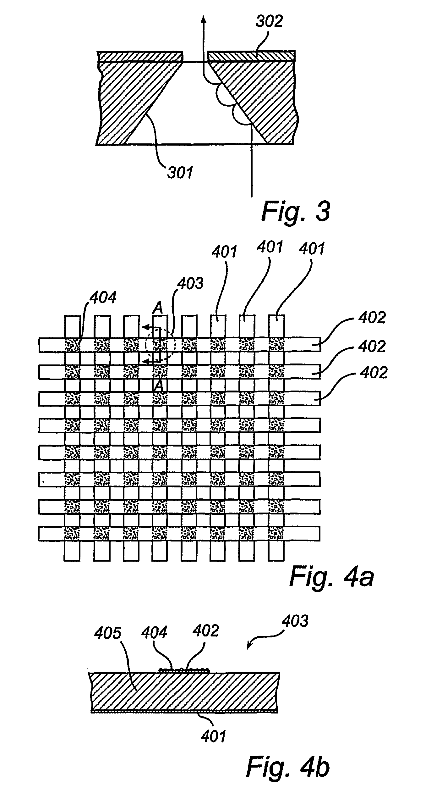
[0006] Preferably, the cathodes are parallel cathode strips and the gate electrodes are parallel gate strips, which extend in a direction perpendicular to the cathode strips, such that emitter elements are formed at intersections between cathode strips and gate strips, which emitter elements are addressable by activating the corresponding cathode and gate strips. Preferably, each such emitter element has a corresponding picture element in a display screen, which is associated with the anode, and a corresponding electron guiding funnel in the electron beam guidance element. This allows large but thin display devices to be produced.
[0009] Preferably, the cathode strip comprises cut-outs in this surface broadening. This improves the electron emitting capability of the emitter element, since most electrons are emitted from edge portions of the cathode.
[0013] In a preferred embodiment a gate strip may comprise a cut-out in the area of an emitter element, which cut-out may preferably substantially correspond to the extension of a corresponding cathode surface in the area of the emitter element, so as to obtain minimal overlap therebetween. This reduces the emitter-gate capacitance, which lowers the energy consumption due to switching losses of the display device.
[0014] The insulating layer may be a solid layer, but preferably has two sub-layers with different permittivities (εr), the sub-layer with the highest permittivity being closest to the gate electrodes. This creates a higher field strength at the emitter sites, given the same total insulator thickness and the same applied gate voltage.
[0015] In a preferred embodiment the display device further comprises auxiliary gate electrodes, disposed substantially in the same plane as the cathodes. This provides more degrees of freedom in forming the field around the electron emitting area of the cathode.

Problems solved by technology

A problem with display devices comprising such field emission structures is that the anode field influences the electron emission from the carbon nanotube (CNT) emitters.
Lowering the anode voltage is no useful solution to this problem, since this may lead to divergence of the electron beams, which is undesirable in a display device.

Method used


Image

  • Display device
  • Display device
  • Display device

Examples


Embodiment Construction

[0028]FIG. 1 shows a sectional view of a display device according to the prior art. A first substrate 101 is used as a display screen and is connected to an anode (A). On a second substrate 102, a number of gate electrodes 103 are formed, the section through one of them is shown in the Fig. On top of the gate-electrode layer an insulating layer 104 is disposed, which separates the gate electrodes 103 from a number of cathodes (C) 105 which are formed on the insulating layer 104. The cathodes 105 are strips that extend in a direction perpendicular to the direction of the gate electrode strips 103. At the intersection between a gate electrode strip 103 and a cathode strip 105, an emitter element 106 is provided, such that the gate electrode 103 may be used to control the emission of electrons from the cathode 105 at the area of the emitter element 106. This emitter structure may be called an under-gate emitter, since the gate is placed under the cathode, and has the advantage that the...


PUM


Abstract

The invention relates to a display device having under-gate emitters, i.e. emitters where the gates (203) are arranged under the cathodes (205), beneath an insulating layer (204). In order to protect the emitters from a high electric field from an anode (A), an electron guidance element (207) is placed between the emitters and the anode. This allows a relatively low voltage swing to be used for controlling the electron emission from the emitters from the on-state to the off-state.

Description

TECHNICAL FIELD [0001] The invention relates to a display device comprising a field emission structure having first and second planar, parallel substrates which are spaced apart so as to form a gap therebetween, an anode, which is arranged at the first substrate, a number of cathodes, which are disposed in a plane on the second substrate, on the side facing the first substrate, a number of gate electrodes for controlling electron emission from the cathodes, which gate electrodes are disposed in a plane on the second substrate, under the cathodes, and are separated from the cathodes by an electrically insulating layer. BACKGROUND OF THE INVENTION [0002] Such a field emission structure is disclosed in U.S. Pat. No. 6,420,726. In the structure, gate electrodes are formed as parallel strips on a substrate and a continuous layer of insulating material is disposed on top of the gate electrodes. Cathodes are formed as parallel lines on top of the insulating layer, which lines are perpendic...

Claims


Application Information

Patent Timeline
Patent Type & Authority Applications(United States)
IPC IPC(8): H01J9/02H01J29/46H01J29/48H01J31/12
CPCH01J29/467H01J2329/46H01J31/127H01J29/482
Inventor VAN DER POEL, WILLIBRORDUS A. J. A.VAN ZUTPHEN, TOMWIERENGA, HARM ALBERTDEEBEN, JOSPHUS PAULUS AUGUSTINUSCOSMAN, EDWARD CHRISTIAANGILLIES, MURRAY FULTON
Owner KONINKLIJKE PHILIPS ELECTRONICS NV
Learn More