Antenna device and radio communication terminal

a radio communication terminal and antenna technology, applied in the direction of multi-antenna systems, resonant antennas, independent non-interacting antenna combinations, etc., can solve the problems of narrow receivable frequency bandwidth of antennas installed to radio communication terminals, deterioration of antenna performance, and deterioration of antenna gain and reception sensitivity, so as to achieve wide bandwidth and widen the frequency bandwidth of main antennas

a radio communication terminal and antenna technology, applied in the direction of multi-antenna systems, resonant antennas, independent non-interacting antenna combinations, etc., can solve the problems of narrow receivable frequency bandwidth of antennas installed to radio communication terminals, deterioration of antenna performance, and deterioration of antenna gain and reception sensitivity, so as to achieve wide bandwidth and widen the frequency bandwidth of main antennas

US20070052599A1Inactive Publication Date: 2007-03-08LENOVO INNOVATIONS LTD HONG KONG

Image

  • Antenna device and radio communication terminal
  • Antenna device and radio communication terminal
  • Antenna device and radio communication terminal

Examples


Embodiment Construction

[0037] The following describes a preferred embodiment to practice the present invention. However, the scope of the invention is not limited to the embodiment shown in the drawings.

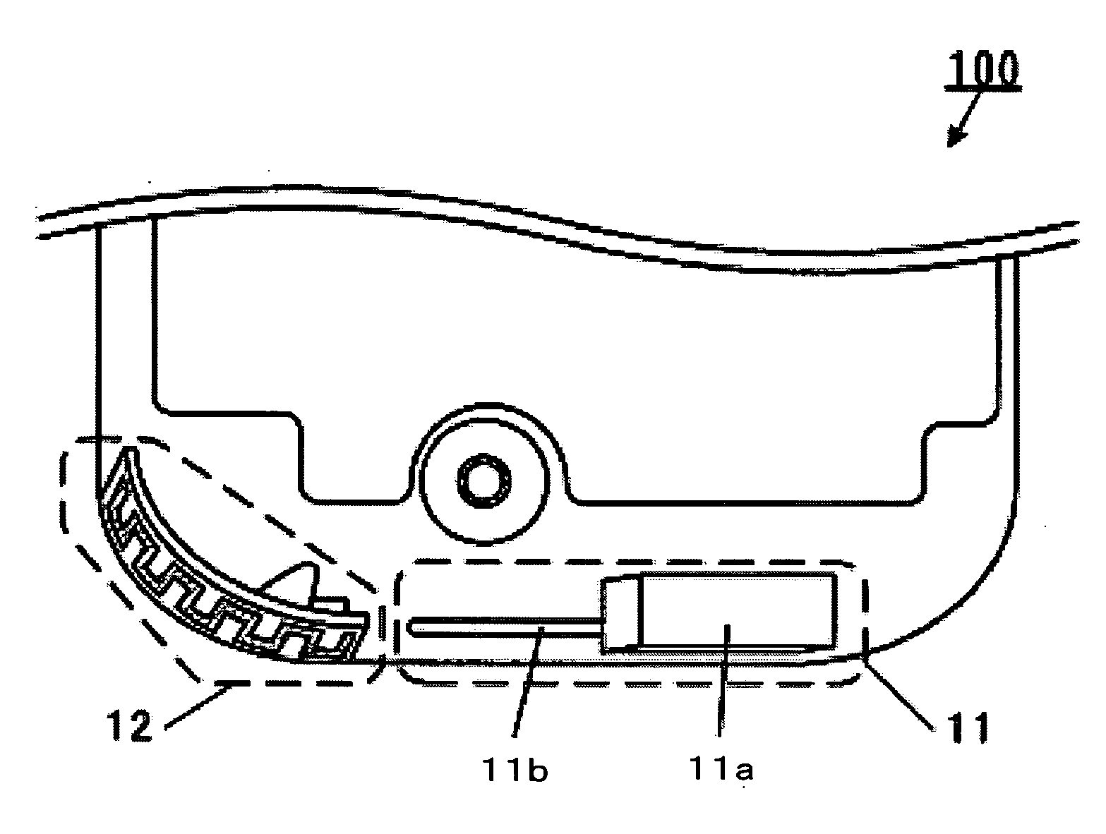
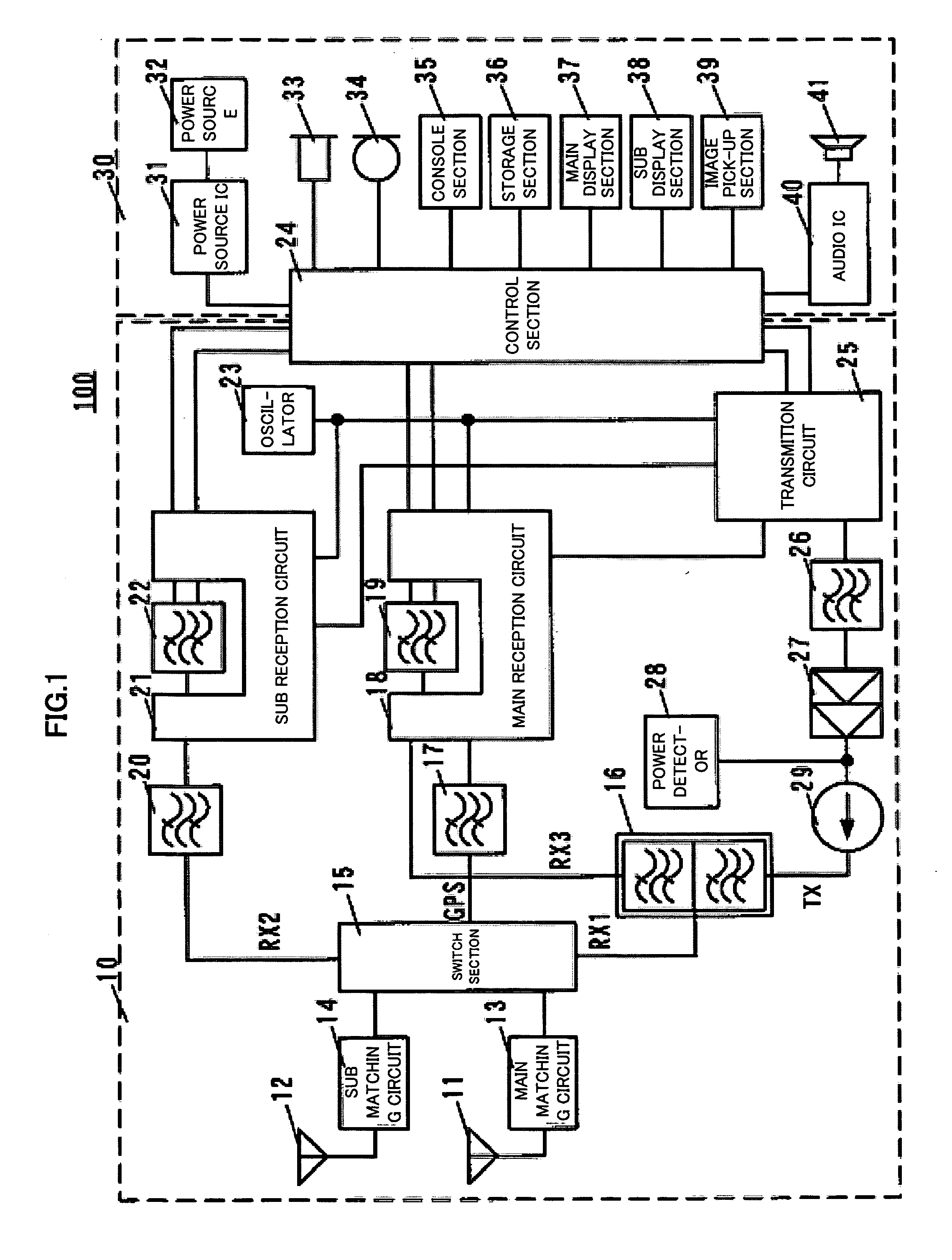
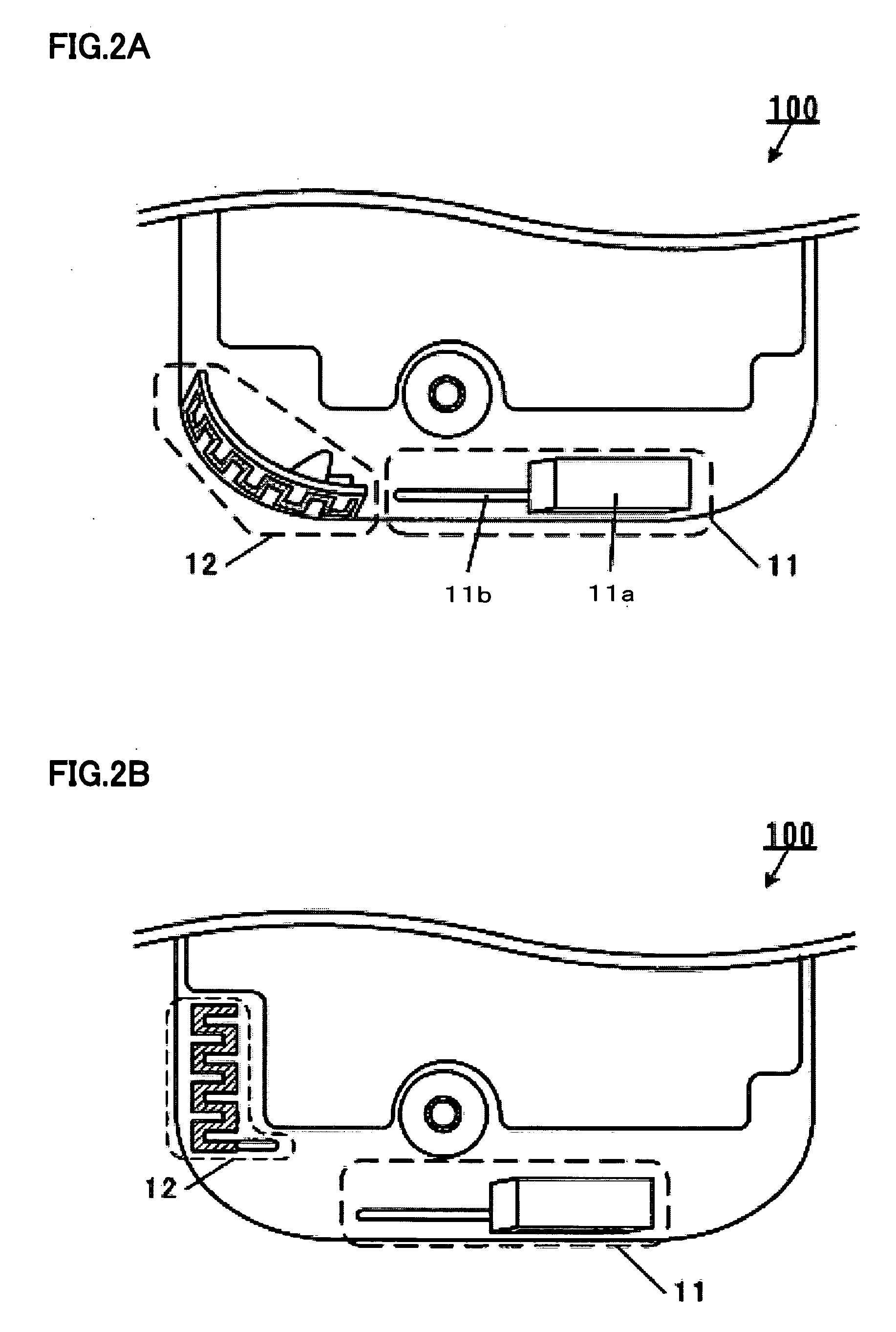
[0038]FIG. 1 shows the internal structure of a portable communication terminal 100 as a radio communication terminal comprising an antenna device according to the present invention. In the present embodiment, a cellular phone terminal is used as a portable communication terminal 100.

[0039] As shown in FIG. 1, the portable communication terminal 100 comprises a transmission-reception section 10 and a terminal-function section 30.

[0040] Here, the transmission-reception section 10 comprises a main antenna 11, a sub antenna 12, a main matching circuit 13, a sub matching circuit 14, a switch section 15, a duplexer 16, a GPS reception filter 17, a main reception circuit 18, a main reception filter 19, a first sub reception filter 20, a sub reception circuit 21, a second sub reception filter 22, an oscillator ...


PUM


Abstract

A switching unit which switches the sub antenna, which is for performing diversity reception in cooperation with the main antenna for transmission and reception, from functioning as an antenna to functioning as a parasitic element, or from functioning as a parasitic element to functioning as an antenna, is provided; the main antenna and the sub antenna are provided to be spaced a predetermined distance apart so that multiple resonance can be generated by electromagnetic coupling, and the sub antenna is made to function as a parasitic element to generate multiple resonance, widening the frequency band width within which the main antenna can transmit and receive a radio wave.

Description

BACKGROUND OF THE INVENTION [0001] 1. Field of the Invention [0002] The present invention relates to an antenna device and a radio communication terminal that receive radio wave signals. [0003] 2. Description of the Related Art [0004] In recent years, diversity reception is employed in radio communication terminals including cellular phones. In the diversity reception, a transmitter-receiver antenna element and a receive-only antenna element are connected to a reception device, and signals received by the antenna elements are selected in accordance with the reception electric field intensity, so that, of the signals received by the antenna elements, a signal whose reception electric field intensity is the higher is selected. Or, the signals received by the respective antenna elements are combined. [0005] On the other hand, further downsizing and high-functionalization of radio communication terminals is desired. Thus, it becomes an absolute must, to make the radio communication term...

Claims


Application Information

Patent Timeline
08 Mar 2007
Publication
US20070052599A1
IPC
H01Q1/24; H01Q3/24; H01Q5/10; H01Q21/30; H04B7/08
CPC
H01Q1/243; H04B7/0825; H01Q21/28; H01Q9/0414; H01Q9/40; H04B1/401; H04B1/3833
Inventors
SHIMIZU, TAKAYUKI; ENOSHIMA, RYOUICHI