
3D image processing apparatus and method

Inactive Publication Date: 2007-03-08
SAMSUNG ELECTRONICS CO LTD
View PDF9 Cites 50 Cited by
  • Summary
  • Abstract
  • Description
  • Claims
  • Application Information

AI Technical Summary

Benefits of technology

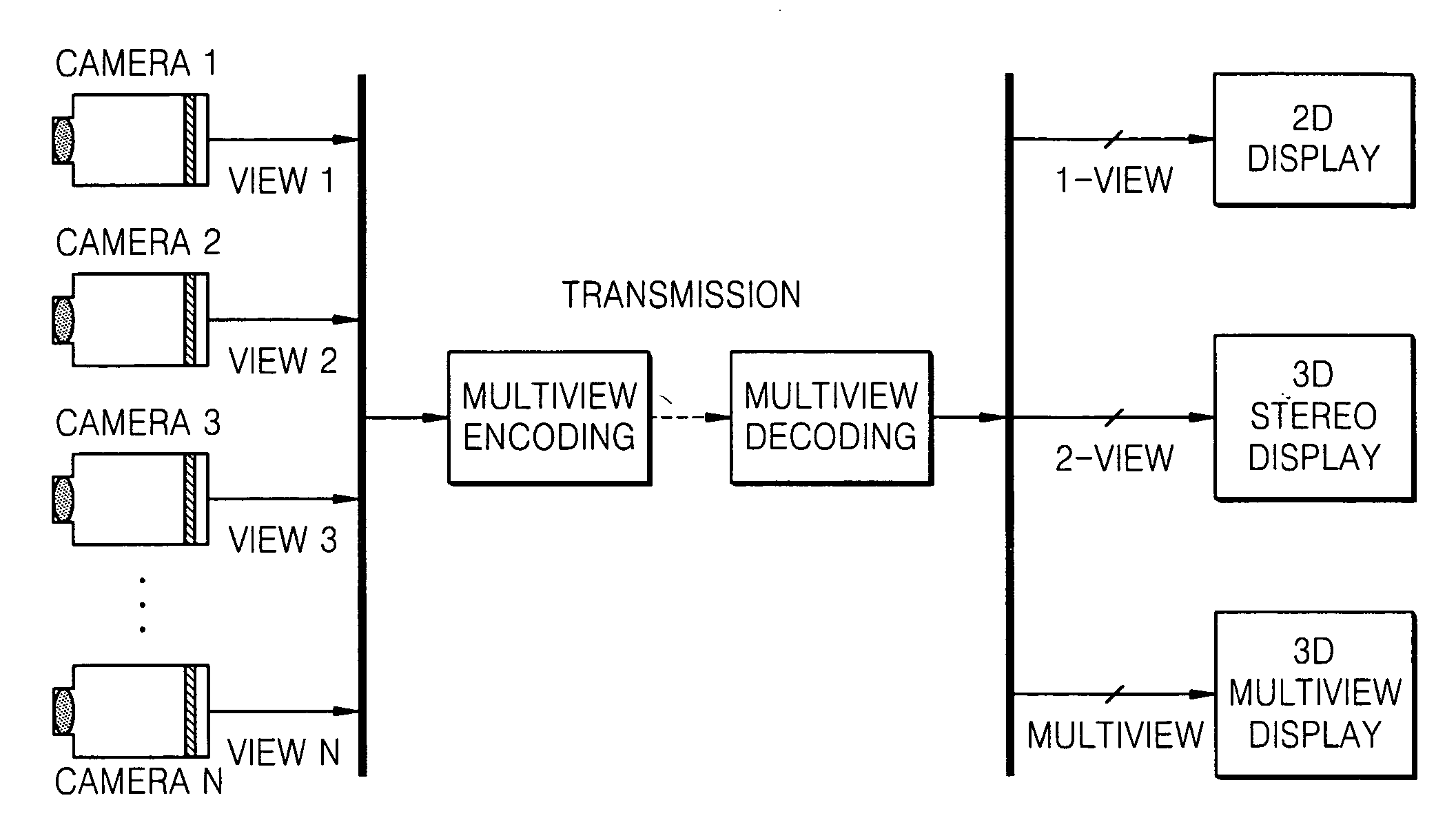
[0008] Embodiments of the present invention provide an image processing method and apparatus which can be used to control convergence of an image acquired by a multiview camera to use the image for a three-dimensional (3D) stereo display.
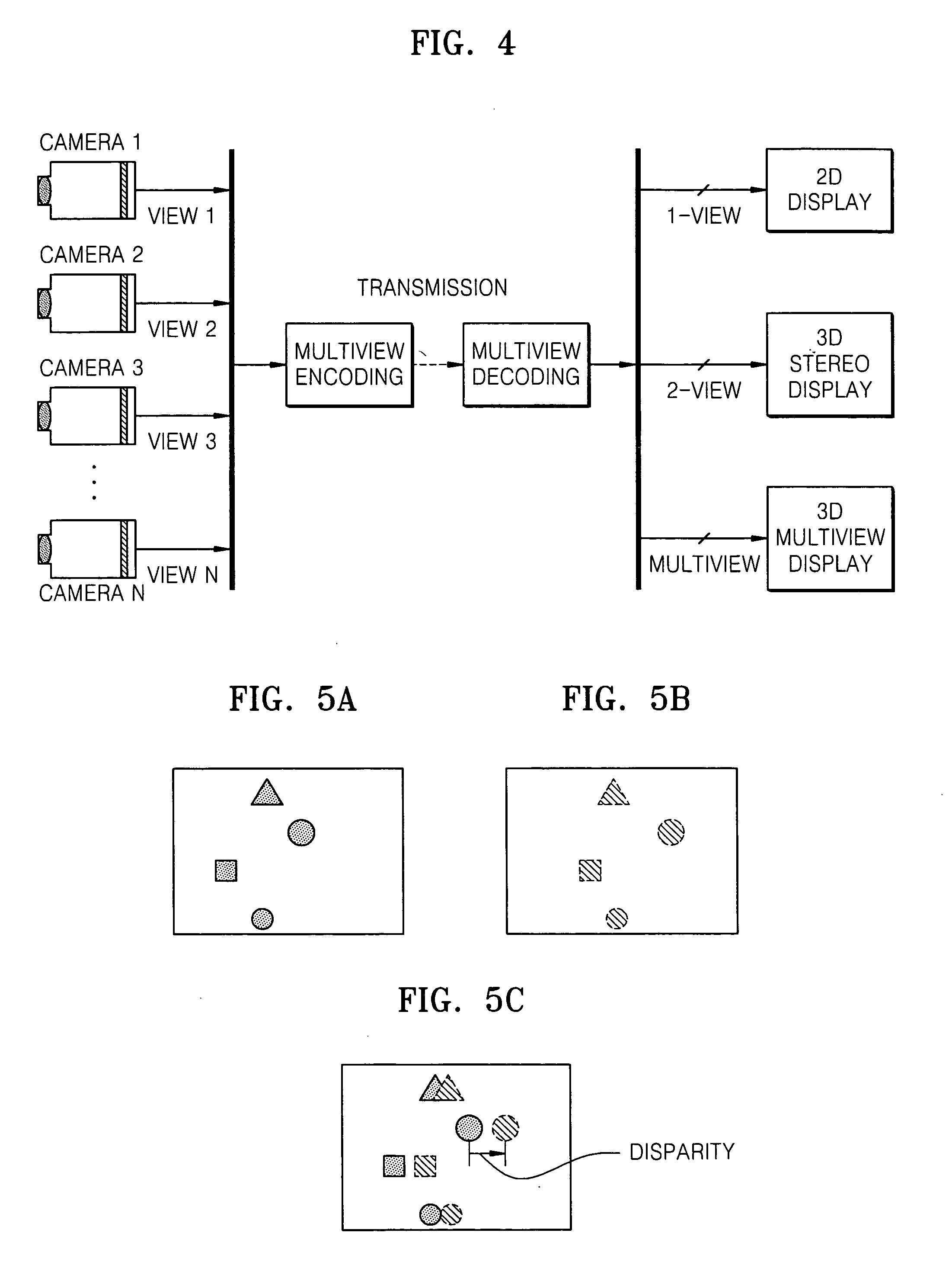
[0010] Embodiments of the present invention also provide an image processing method and apparatus which can be used to output a stable image by preventing jitter when a receiving end which receives and displays an image adjusts the disparity of the image and outputs the disparity-adjusted image.
[0018] The scale factor may be M / (M−D), where M is a horizontal size of the image and D is a value corresponding to half the horizontal movement value, and the scaling unit may remove a height of the scaled image which has become larger than that of an original image by scaling such that the scaled image becomes the same size as the original image.
[0022] According to another aspect of an embodiment of the present invention, there is provided an image processing method including: receiving a 3D image and dividing the 3D image into a left-eye image and a right-eye image; estimating disparities between the left-eye image and the right-eye image; determining a horizontal movement value for the left-eye image and the right-eye image using the estimated disparities; horizontally moving the left-eye image and the right-eye image based on the determined horizontal movement value; vertically and horizontally scaling the disparity-adjusted left-eye image and right-eye image by a predetermined scale factor to compensate for portions of the disparity-adjusted left-eye image and right-eye image which are cut as a result of the horizontal movement.

Problems solved by technology

However, when a display environment is different from a production environment, for example, when a 3D image produced using a multiview camera is displayed on a stereoscopic 3D display or when displays of different sizes are used for producing and displaying a 3D image, conventional 3D displays cannot display a 3D image as intended.

Method used


Image

  • 3D image processing apparatus and method
  • 3D image processing apparatus and method
  • 3D image processing apparatus and method

Examples


Embodiment Construction

[0041] The present invention will now be described more fully with reference to the accompanying drawings, in which exemplary embodiments of the invention are shown. The invention may, however, be embodied in many different forms and should not be construed as being limited to the embodiments set forth therein; rather, these embodiments are provided so that this disclosure will be thorough and complete, and will fully convey the concept of the invention to those skilled in the art.

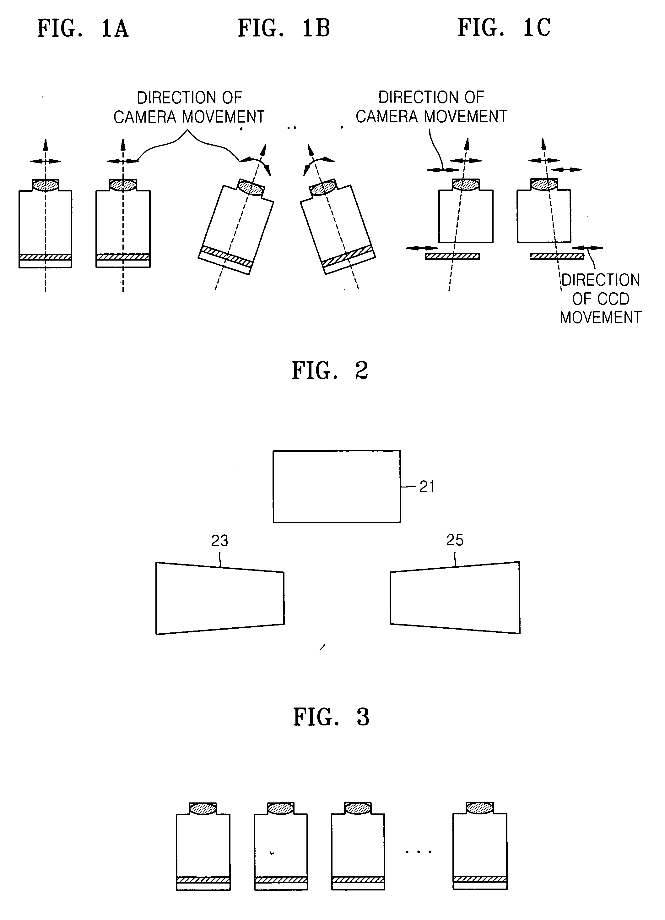
[0042] The structure of a camera which produces a real image will now be described with reference to FIGS. 1 and 3.

[0043]FIG. 1 illustrates various types of stereoscopic cameras. FIG. 1A illustrates a parallel stereoscopic camera. The alignment of the parallel stereoscopic camera is simple. However, since the parallel stereoscopic camera does not have a convergence function, it cannot take a photograph of an image taking into consideration characteristics of human vision. Thus, the filmed image cannot be...


PUM


Abstract

A three-dimensional (3D) image processing apparatus and method are provided for use with a 3D, image divided into a left-eye image and a right-eye image. The apparatus includes a disparity estimation unit estimating disparities between the left-eye image and the right-eye image; a horizontal movement determination unit determining a horizontal movement value for the left-eye image and the right-eye image using the estimated disparities; and a horizontal movement unit horizontally moving the left-eye image and the right-eye image based on the determined horizontal movement value. In the method and apparatus, a receiving end which receives and displays a 3D image can enhance 3D effects and reduce eye fatigue by adjusting the disparity of the 3D image.

Description

[0001] This application claims the priority of Korean Patent Application No. 10-2005-0082000, filed on Sep. 3, 2005, in the Korean Intellectual Property Office, the disclosure of which is incorporated herein in its entirety by reference. BACKGROUND OF THE INVENTION [0002] 1. Field of the Invention [0003] Apparatuses and methods consistent with the present invention relate processing a three-dimensional (3D) image, and more particularly, to an image processing apparatus and method for adjusting the disparity of an input 3D image and stably displaying the 3D image. [0004] 2. Description of the Related Art [0005] Conventional three-dimensional (3D) displays display a 3D image by projecting images having different disparities to the left and right eyes of a user using a 2D flat display and tools such as a film-type micro-polarizer, a parallax barrier, and a lenticular lens. Such 3D displays may be classified into stereoscopic 3D displays and multiview 3D displays according to the number...

Claims


Application Information

Patent Timeline
IPC IPC(8): H04N13/00H04N13/239H04N13/243
CPCG06T7/0022H04N13/0022H04N2213/002H04N13/0239H04N13/0242H04N13/0033H04N13/243H04N13/144H04N13/239H04N13/128
Inventor HA, TAE-HYEUNSHESTAK, SERGEY
Owner SAMSUNG ELECTRONICS CO LTD
Learn More