
Fiber-optic sensor coil and current or magnetic-field sensor

a technology of current or magnetic field and fiber optic sensors, applied in the field of fiberoptic sensor systems, can solve the problems of inflexible sensor fibers, inability of sensors to measure electric current flowing in current conductors, and disadvantageous fixed coil shapes for transport and installation, and achieve the effect of high measurement accuracy

Active Publication Date: 2007-03-08
HITACHI ENERGY SWITZERLAND AG
View PDF6 Cites 20 Cited by
  • Summary
  • Abstract
  • Description
  • Claims
  • Application Information

AI Technical Summary

Benefits of technology

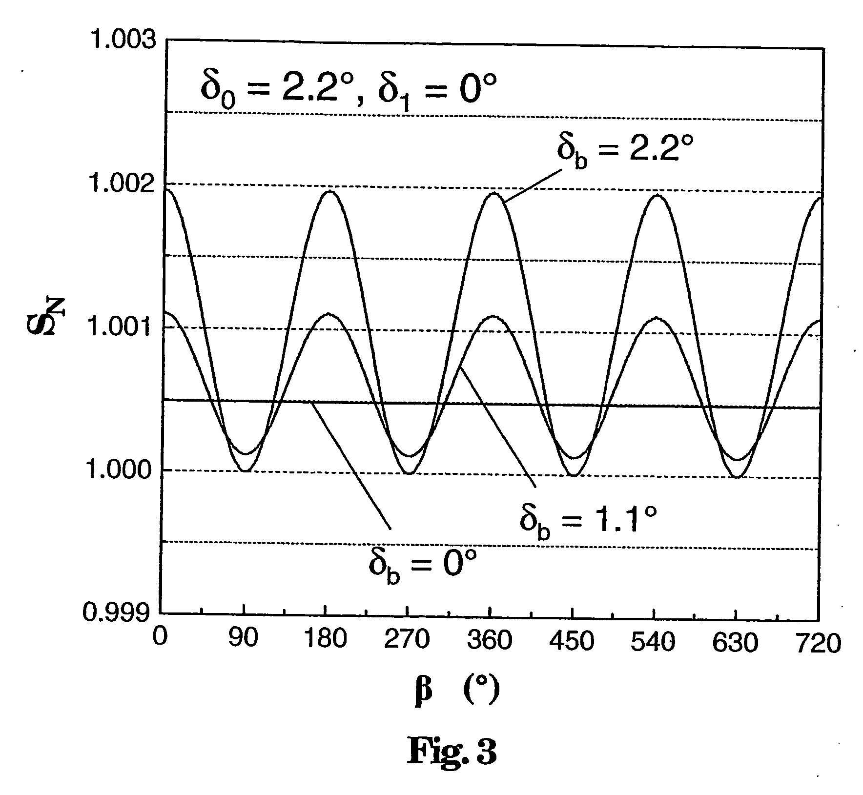
[0007] In exemplary embodiments, high measurement accuracy can be achieved even when the sensor coil is repeatedly removed and refitted, and without this requiring renewed calibration of the sensor. An exemplary aim is for it to be possible to calibrate the sensor during production (of the sensor coil or of the sensor), then to change the sensor fiber to a different shape, and then to install it at the usage location once again forming a coil without any need to recalibrate the sensor.

Problems solved by technology

A sensor head such as this can have the disadvantage that its sensor fiber is not flexible.
The sensor cannot be fitted for measurement of an electric current flowing in a current conductor without opening the current conductor.
If the coil diameter is large, a fixed coil shape is also disadvantageous for transport and installation.
If the coil of a sensor such as this were designed to be flexible, this could have a disadvantageous effect on its accuracy.
Measurements with an accuracy in the one in a thousand range are not possible with a sensor such as this, and it is more difficult to transport and install the sensor head in confined spatial conditions.

Method used


Image

  • Fiber-optic sensor coil and current or magnetic-field sensor
  • Fiber-optic sensor coil and current or magnetic-field sensor
  • Fiber-optic sensor coil and current or magnetic-field sensor

Examples


Embodiment Construction

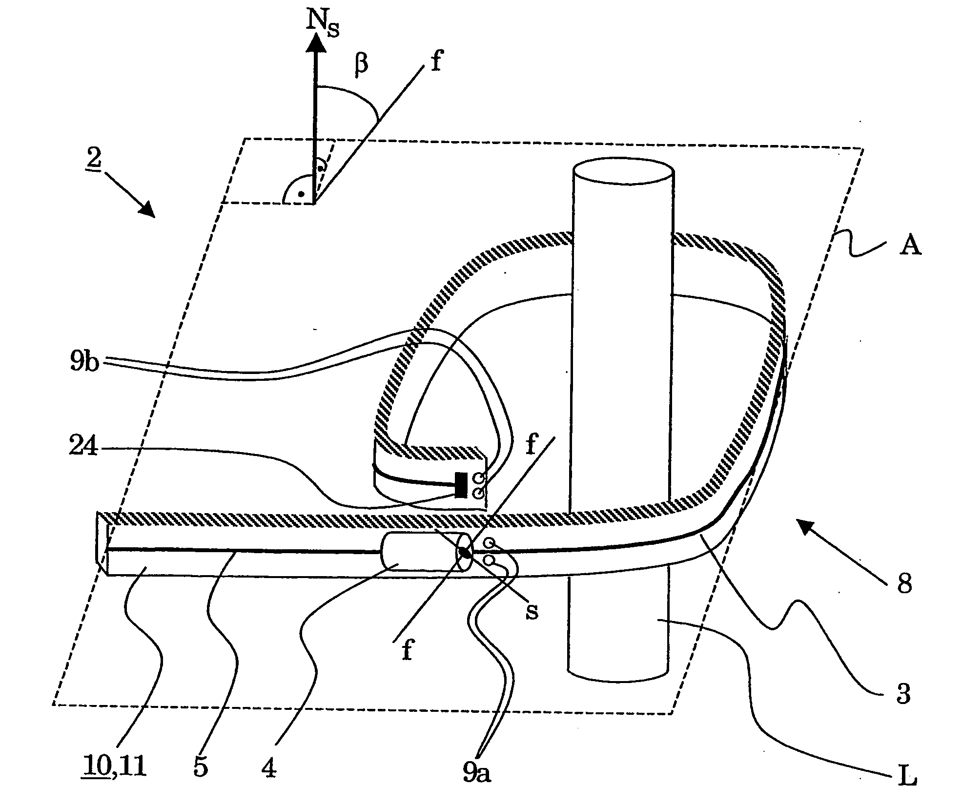
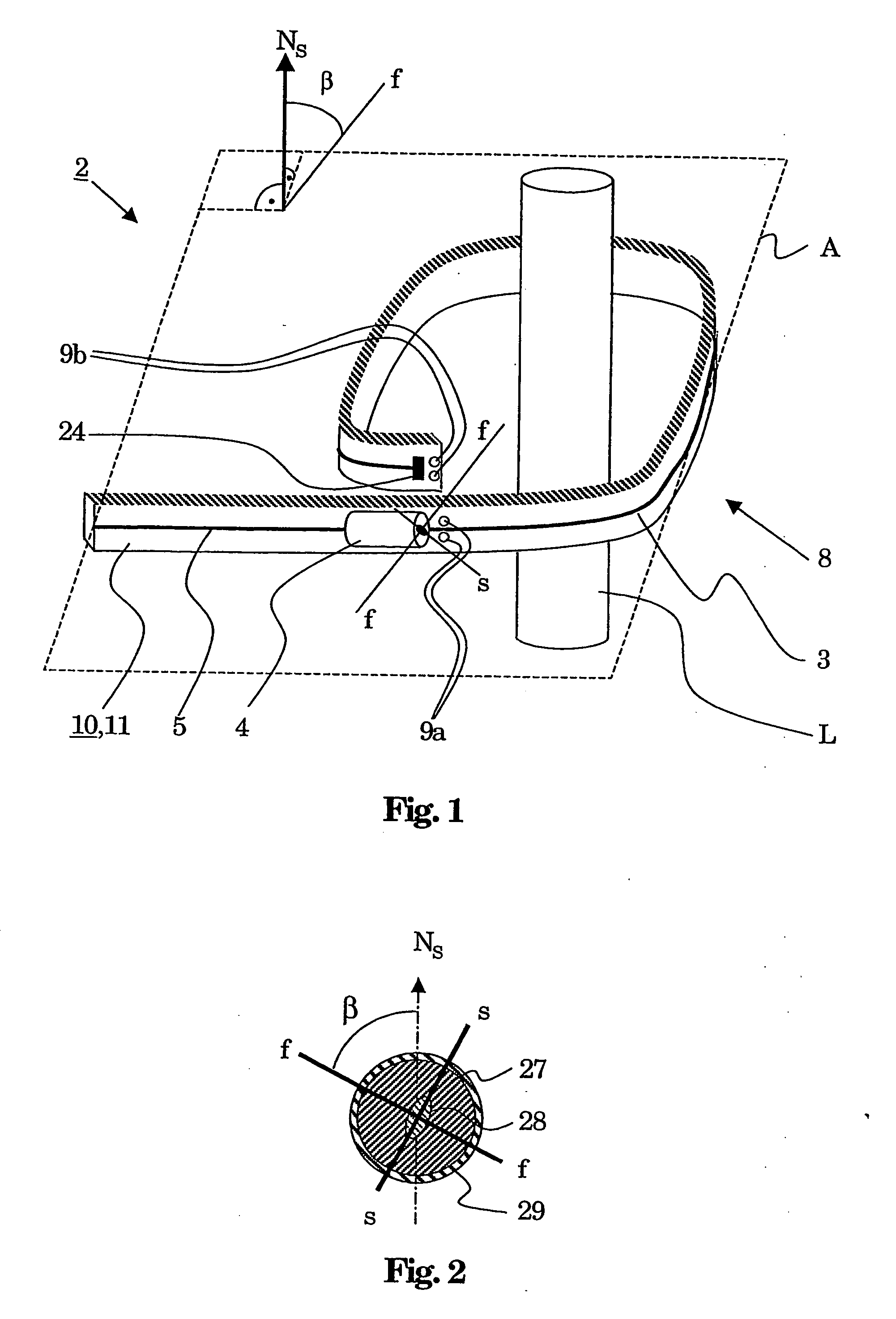
[0018] An exemplary fiber-optic sensor head is disclosed for a current or magnetic-field sensor having an optical fiber which includes a magnetooptically active sensor fiber which is optically connected to at least one polarization-defining element, wherein the sensor fiber can be arranged in the form of a coil around a conductor which carries the current to be measured or in a magnetic field to be measured, with the coil defining a coil plane with a surface normal, and with the at least one polarization-defining element having a marked or preferred axis.

[0019] The sensor head can be bendable (flexible) in the area of the sensor fiber, and an adjustment means can be provided for adjustment of a predeterminable angle β between the marked axis and the surface normal or for adjustments of predeterminable angles β, β′ between the marked axes and the surface normal. When there are two polarization-defining elements, the angle between a marked axis of one polarization-defining element an...


PUM


Abstract

A fiber-optic sensor head is disclosed for an optical current or magnetic-field sensor which can have an optical fiber which includes a magnetooptically active sensor fiber which is optically connected to at least one polarization-defining element. The sensor fiber can be arranged in a magnetic field to be measured or around a conductor carrying current to be measured and can be in the form of a coil, with the coil defining a coil plane (A) with a surface normal (Ns), and with the at least one polarization-defining element having a marked axis (f). The sensor head can be flexible in the area of the sensor fiber, and an adjustment means can be provided for adjustment of a predeterminable angle β between the marked axis,(f) and the surface normal (Ns) or for adjustment of predeterminable angles β, β′ between the marked axes (f) and the surface normal (Ns).

Description

RELATED APPLICATIONS [0001] This application is based on and claims priority under 35 U.S.C. §119 to European Application No. 04405308.0, filed May 13, 2004, and is a continuation application under 35 U.S.C. §120 of International Application No. PCT / CH2005 / 00221, filed Apr. 21, 2005, designating the United States, the entire contents of both of which are hereby incorporated by reference.TECHNICAL FIELD [0002] A fiber-optic sensor system is disclosed, as is a sensor head, a current or magnetic-field sensor, and a high-voltage installation. A method is disclosed for production of a sensor head. PRIOR ART [0003] One such sensor head is disclosed, for example, in EP 0 856 737 A1. This document describes a fiber-optic current sensor having a sensor head which contains a sensor fiber, which is arranged in a capillary and forms a sensor coil. The fiber coating is removed from the sensor fiber, and the fiber is then thermally treated in order to remove mechanical stresses which lead to dist...

Claims


Application Information

Patent Timeline
IPC IPC(8): G01B9/02G01R15/24
CPCG01R35/005G01R15/247
Inventor BOHNERT, KLAUSGABUS, PHLIPPENEHRING, JUERGENBRANDLE, HUBERT
Owner HITACHI ENERGY SWITZERLAND AG
Learn More