Light scanning device and image forming apparatus using the same

Active Publication Date: 2007-03-08
SHARP KK
View PDF4 Cites 10 Cited by
  • Summary
  • Abstract
  • Description
  • Claims
  • Application Information

AI Technical Summary

Benefits of technology

[0026] Further, in addition to the above common effect that is obtained from the first to fifth aspects of the invention, each aspect of the invention has the following effect.
[0027] Detailedly, according to the second aspect of the invention, it is possible to suppress the vibration of the optical system which would exert print quality.
[0028] According to the third aspect of the invention, it is possible with a simple configuration to suppress vibrations in the optical system.
[0029] According to the fourth aspect of the invention, it is possible to suppress the vibration that propagates from the polygon motor toward the attachment portions that lie along the a

Problems solved by technology

However, high-speed image forming apparatus configurations suffer the problem of increased vibrations due to rotations of motors for the apparatus and rotations of apparatus drivers, etc., during the operation of the machine.
In a system that performs deflection scanning using a polygon motor, the polygon motor is prone to be the source of vibrations because it rotates at high speed.
However, it is true that the above methods are effective when the optical scan uni

Method used


Image

  • Light scanning device and image forming apparatus using the same
  • Light scanning device and image forming apparatus using the same
  • Light scanning device and image forming apparatus using the same

Examples


Example

[0044] Now, the best mode for carrying out the present invention will be described with reference to the drawings.

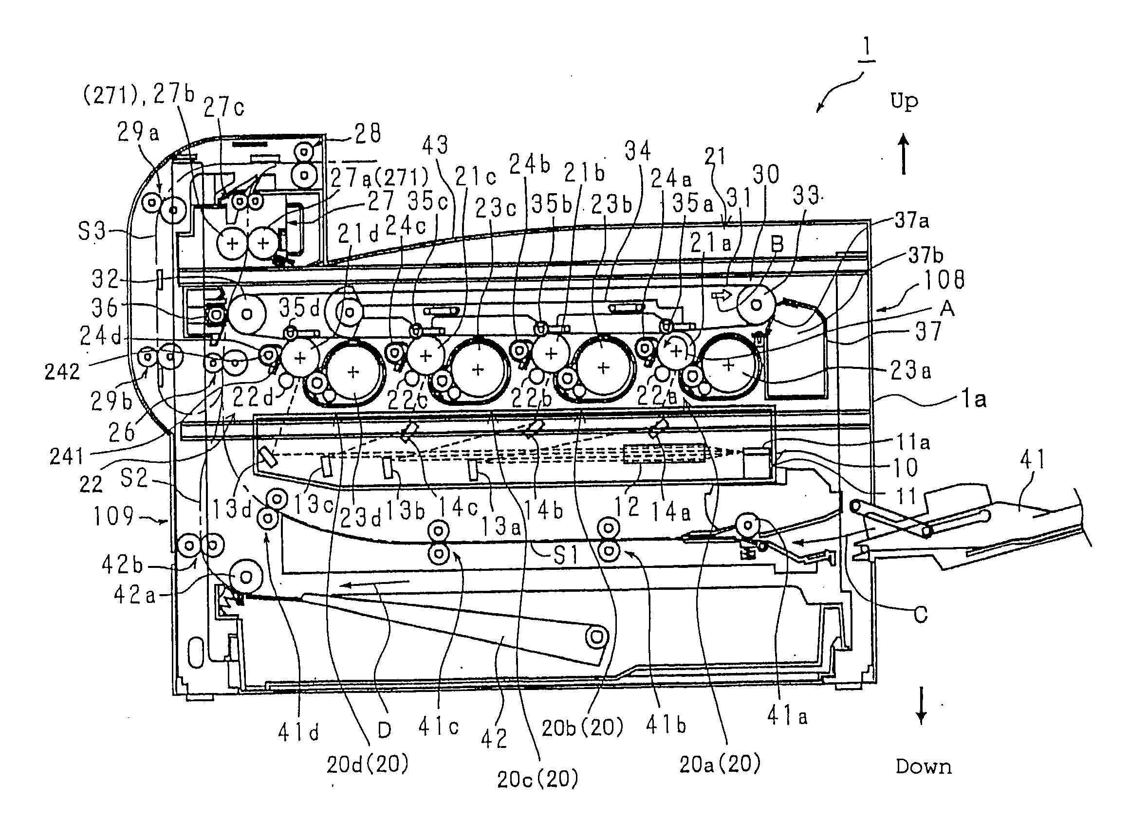
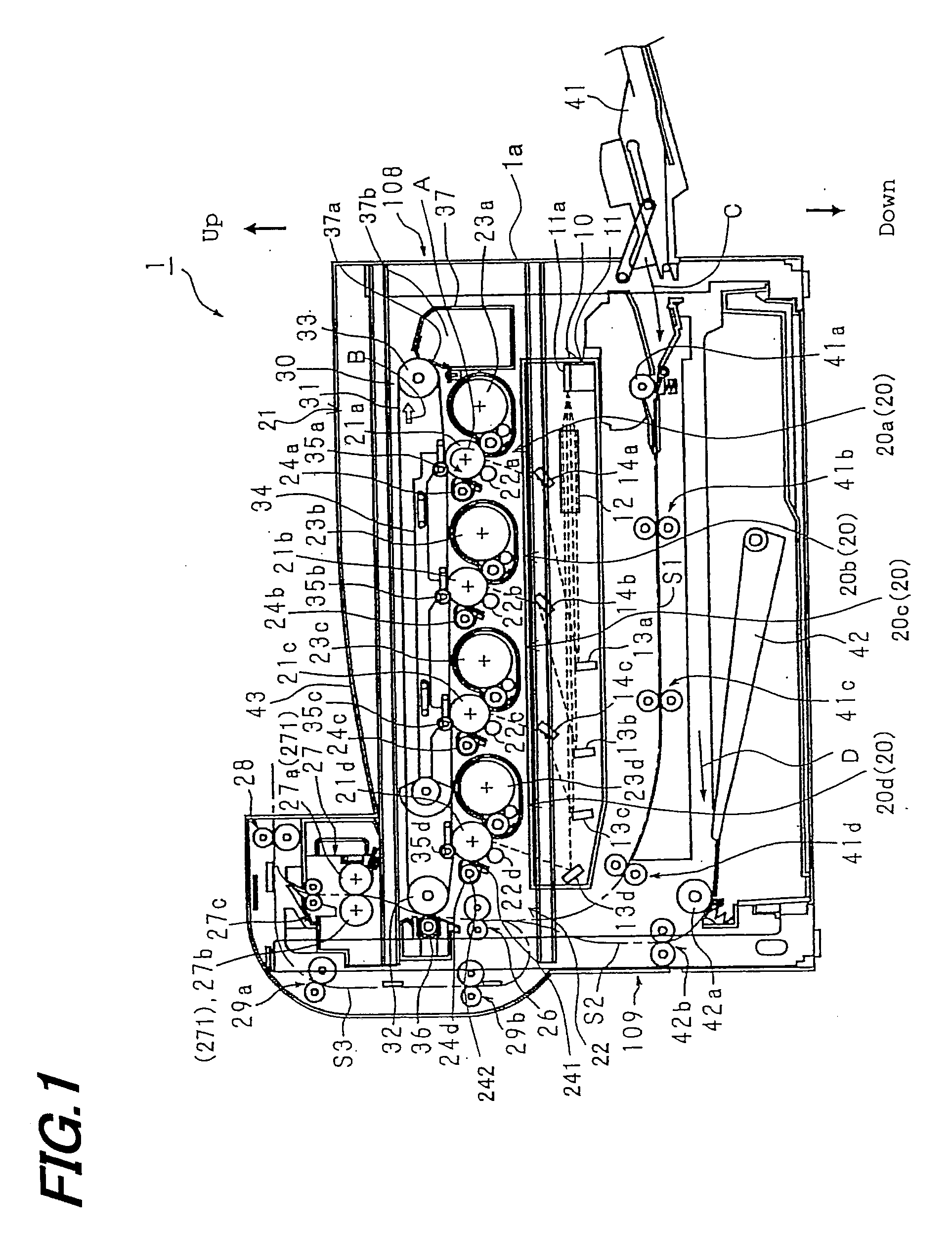
[0045]FIG. 1 is an illustrative diagram showing the overall configuration of an image forming apparatus according to the embodiment of the present invention, showing one example of the mode for carrying out the present invention.

[0046] As shown in FIG. 1, an image forming apparatus 1 of the present embodiment includes: a plurality of image forming means or namely, process printing units (developing means) 20 (20a, 20b, 20c and 20d) each having a photoreceptor drum (electrostatic latent image bearer) 21 (21a, 21b, 21c or 21d) for supporting a developer image (which will be referred to as “toner image” hereinbelow) formed with a developer (which will be referred to as “toner” hereinbelow) corresponding to the color of color-separated image information; an exposure unit (light scanning device) 10 for creating electrostatic latent images on photoreceptor drums 21 of indivi...


PUM


Abstract

In an exposure unit including: a laser scanning unit emitting a multiple number of beams; a polygon mirror for deflecting the multiple beams by reflection with the same facet; an optical system including optical elements for leading the beams correspondingly to a multiple number of photoreceptor drums laid out along an auxiliary scan direction, the bottom of a casing of the exposure unit to which the polygon mirror and the optical elements arranged along the directions of the beams emitted from the polygon mirror are attached is constructed so that the attachment portions of individual optical elements for each beam are differentiated in thickness from the areas where no attachment portion is formed.

Description

[0001] This Nonprovisional application claims priority under 35 U.S.C. §119(a) on Patent Application No. 2005-322325 filed in Japan on 7 Nov. 2005, the entire contents of which are hereby incorporated by reference. BACKGROUND OF THE INVENTION [0002] (1) Field of the Invention [0003] The present invention relates to a light scanning device and an image forming apparatus using it, and in particular relates to a light scanning unit including a polygon mirror for deflecting a plurality of light beams by reflection with an identical facet thereof; and an optical system for irradiating a plurality of illumination targets, arranged in the auxiliary scan direction, with corresponding beams, as well as relating to an image forming apparatus such as a copier, printer, facsimile machine etc., which includes the aforementioned light scanning device and uses electrophotography as the image forming method thereof. [0004] (2) Description of the Prior Art [0005] Recently, image forming apparatuses ...

Claims


Application Information

Patent Timeline
IPC IPC(8): G02B26/08
CPCB41J2/473G02B26/123G03G15/04036G03G2215/0404G03G15/0435H04N1/12H04N1/506H04N2201/0428H04N1/1135
Inventor WADA, TAKASUMIUEDA, ATSUSHI
Owner SHARP KK
Why Eureka
Try Eureka