Rotating machine and parts of the same
a rotating machine and rotating body technology, applied in the direction of superimposed coating process, liquid/solution decomposition chemical coating, reflex reflector, etc., can solve the problems of deteriorating the working efficiency of the rotating machine, and the inability to prevent particulates such as corpuscular silica and iron oxide particles satisfactorily, so as to achieve the effect of effectively preventing the particulates contained in these gases
- Summary
- Abstract
- Description
- Claims
- Application Information
AI Technical Summary
Benefits of technology
Problems solved by technology
Method used
Image
Examples
embodiment 1
[0026] According to Embodiment 1, parts of a rotating machine deposited on a plated film is characterized in that the plated film containing plated matrix and the fluorocarbon polymer particles is deposited on the surfaces of the parts of a rotating machine.
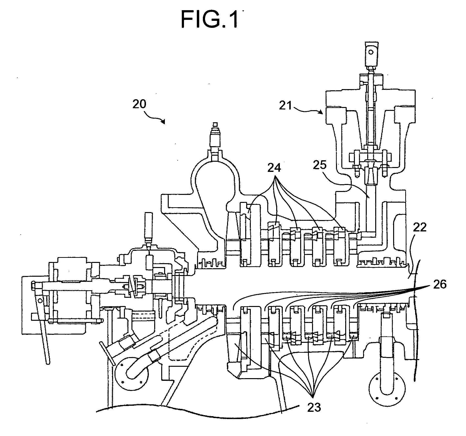
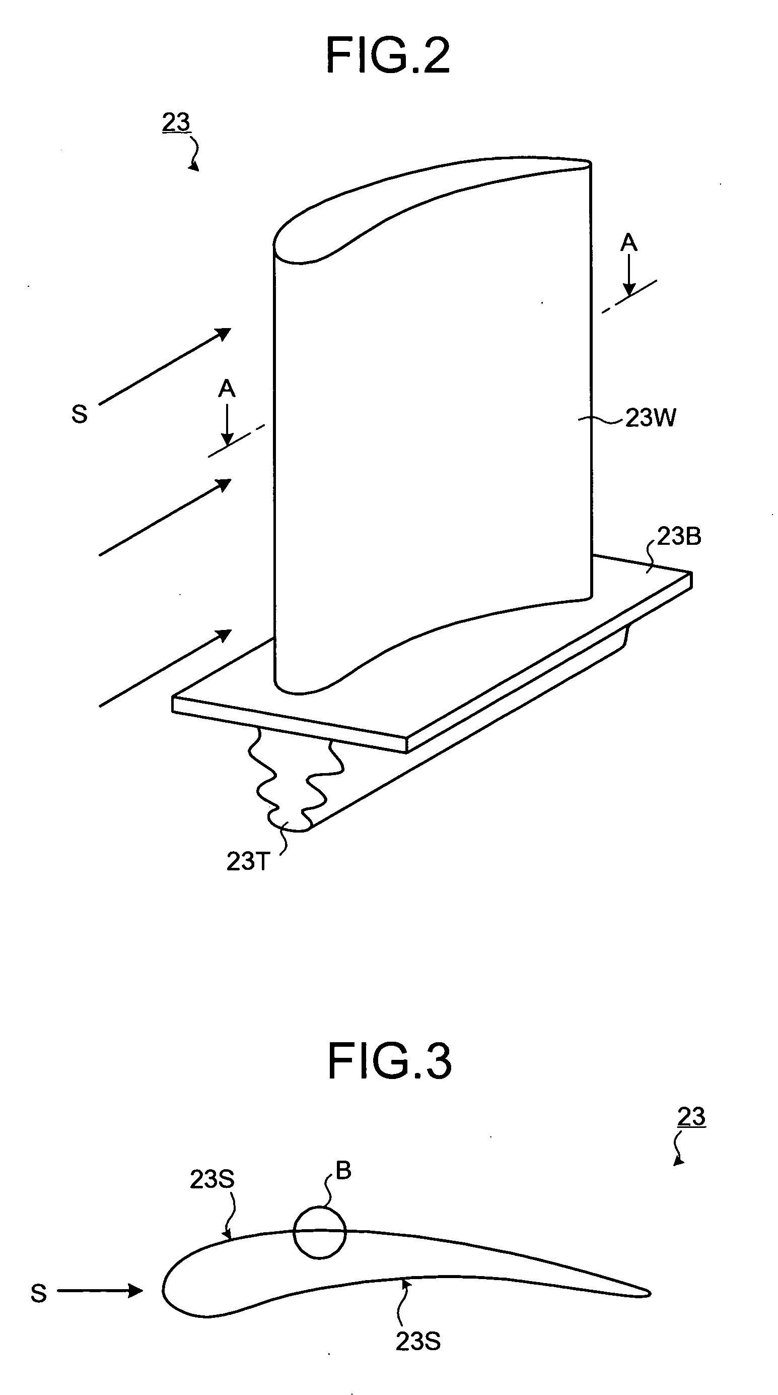
[0027]FIG. 1 is a sectional view showing an area in the vicinity of a turbine chamber, where a steam turbine with moving blades, on the surfaces of which plated films according to the Embodiment 1 are deposited. The steam turbine 20, namely the rotating machine according to the Embodiment 1, converts the steam pressure supplied from a steam feed pipe 25, for which switching is controlled by a steam inlet valve 21, into rotating power. The rotating power is used in, for example, a generator via a reduction gears. A plurality of turbine disks 26 are disposed on a rotor axis 22 to pull out the rotating power. On the circumferences of the turbine disks 26, a plurality of moving blades 23 are disposed in a line to form a rotor moving...
modified example 1
[0049]FIGS. 6A and 6B are schematic views showing the surface of the moving blade according to the Modified Example 1 of the Embodiment 1. The Modified Example 1 has almost the same constitution as the constitution of the Embodiment 1 with an exception that the surface of the moving blade, on which the plated film is deposited, has been modified so that its fatigue strength may be improved. The description of the remaining constitution is omitted because of it being the same as the constitution of the Embodiment 1. It should be noted that the constitution of the Embodiment 1 may be applied to the Modified Example 1 if appropriate.
[0050] In the case where the plated film 10 composed of the intermediate plated film 11 and the plated film 12 containing the fluorocarbon polymer particles are deposited on the surface of the moving blade, the fatigue strength of the base material deteriorates in the process of depositing the plated film 10. As shown in FIG. 6A, the particles contained in...
modified example 2
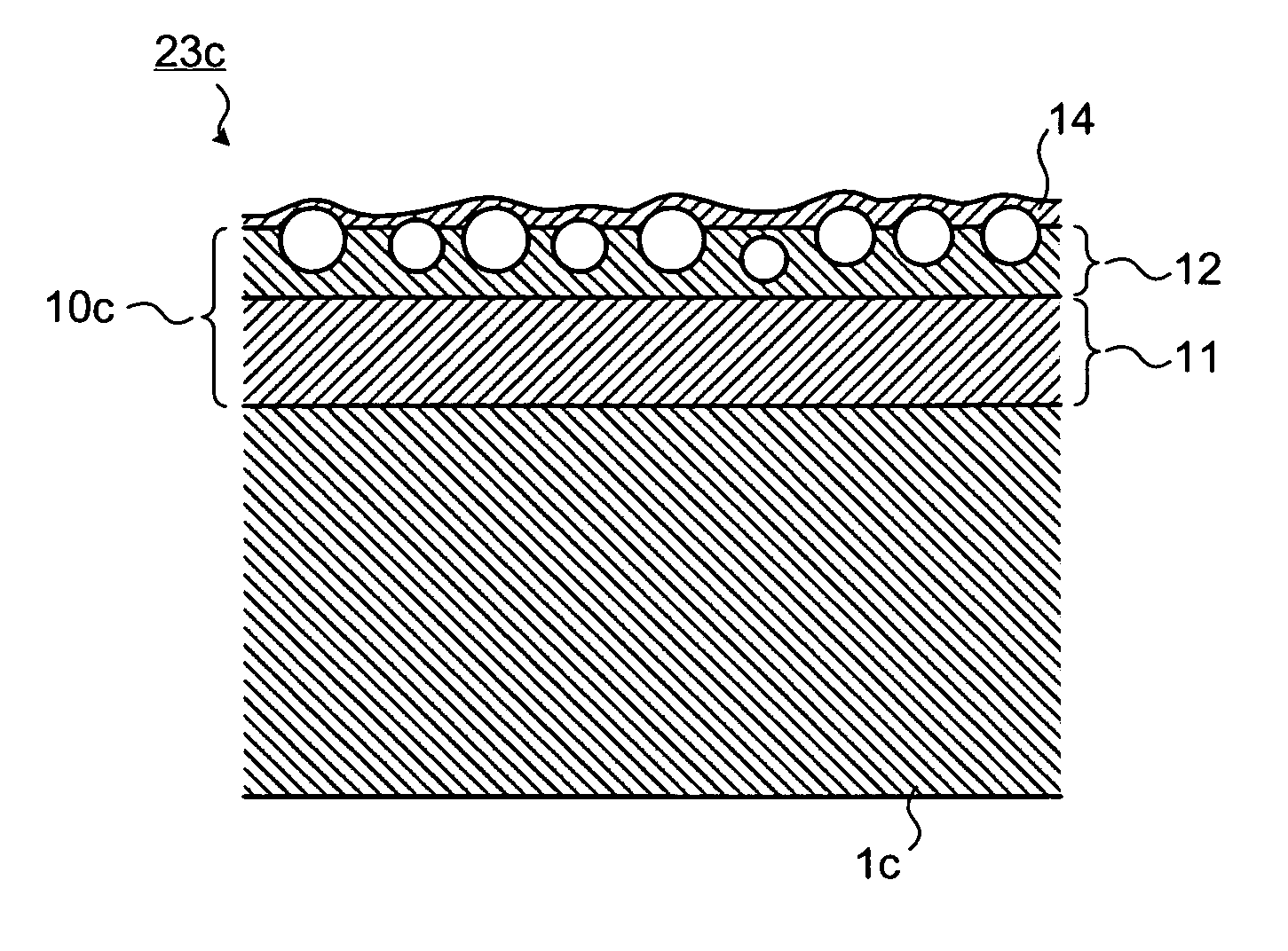
[0054]FIG. 7 is a schematic view showing the surface of the moving blade according to the Modified Example 2 of the Embodiment 1. The Modified Example 2 has almost the same constitution as the constitution of the Embodiment 1 with an exception that an additional fluorocarbon polymer film is provided on the surface of the plated film containing the fluorocarbon polymer particles. The fluorocarbon polymer film is typified by fluorine particle dispersion liquid for Kaniflon (registered trademark) provided from Japan Kanigen Co., Ltd. The remaining constitution is the same as the constitution of the Embodiment 1 and therefore, the description of the remaining constitution is omitted. Note that the constitutions of the Embodiment 1 and the Modified Example 1 may be applied to the Modified Example 2 if appropriate.
[0055] In the plated film 10c provided on the surface of the moving blade 23c, an additional fluorocarbon polymer film 14 is deposited on the plated film 12 containing the fluo...
PUM
| Property | Measurement | Unit |
|---|---|---|
| Fraction | aaaaa | aaaaa |
| Molar density | aaaaa | aaaaa |
| Dynamic viscosity | aaaaa | aaaaa |
Abstract
Description
Claims
Application Information
 - R&D
- Intellectual Property
- Life Sciences
- Materials
- Tech Scout
- Unparalleled Data Quality
- Higher Quality Content
- 60% Fewer Hallucinations
Browse by: Latest US Patents, China's latest patents, Technical Efficacy Thesaurus, Application Domain, Technology Topic, Popular Technical Reports.
© 2025 PatSnap. All rights reserved.Legal|Privacy policy|Modern Slavery Act Transparency Statement|Sitemap|About US| Contact US: help@patsnap.com


