Semiconductor device and method for manufacturing the same

a semiconductor and device technology, applied in the direction of semiconductor devices, basic electric elements, electrical appliances, etc., can solve the problems of increased leakage current from a source electrode or a drain electrode, adverse influence on predetermined operation of semiconductor elements, and difficulty in resisting edge shape, etc., to suppress the variation in properties of elements.

Inactive Publication Date: 2007-03-08
FUJITSU SEMICON LTD
View PDF2 Cites 8 Cited by
  • Summary
  • Abstract
  • Description
  • Claims
  • Application Information

AI Technical Summary

Benefits of technology

[0014] The present invention relates to a semiconductor device and a method for manufacturing the same, and more particularly, relates to a semiconductor device and a method for manufacturing the same, the semiconductor device being capable of suppressing the variation in properties of an element formed in the vicinity of a surface of a semiconductor substrate and in a boundary area of an impurity region formed in the semiconductor substrate at a place apart from the surface thereof.
[0015] In addition, an object of the present invention is to provide a method for manufacturing a semiconductor device, which can solve problems of variation in element properties caused by an inclined shape of an end portion of a resist mask used for defining the above impurity region and, in addition, which can substantially maintain an impurity distribution in a region other than the boundary area of the region in which impurity ion implantation is to be masked.

Problems solved by technology

However, it has been difficult to form an edge shape of a resist which is strictly perpendicular to the surface of the semiconductor substrate, the resist being used for masking high-energy impurity ion implantation.
Hence, in the boundary area of the region in which the high-energy impurity ion implantation is to be masked, the implanted impurity does not reach a predetermined depth, that is, the impurity stays in the region close to the surface of the semiconductor substrate; however, the above phenomenon is not expected beforehand, and a problem may arise in that a preferable predetermined impurity distribution cannot be obtained.
As a result, when a semiconductor element is formed in the boundary area of the region in which the high-energy impurity ion implantation is to be masked, a problem may arise in that predetermined operation of the semiconductor element is adversely influenced.
For example, when the semiconductor element is a MOS (Metal Oxide Semiconductor) transistor, in the vicinity of the impurity region of a drain or a source, a problem may arise in that a leakage current from a source electrode or a drain electrode is increased due to decrease in P-N junction withstand voltage.
However, it has been difficult to implant the impurity for compensation only in the boundary area of the region in which the high-energy impurity ion implantation is to be masked.
That is, the impurity used for compensation is also inevitably implanted in a region other than the boundary area.
Hence, in a region in which the impurity to be compensated for is not present, the concentration of the impurity used for compensation is increased, and as a result, a problem may arise in that a predetermined impurity distribution cannot be obtained.
In addition, in the boundary area of the region in which the high-energy impurity ion implantation is to be masked, in the case in which a conductive type of a region close to the surface of the semiconductor substrate is the same as that of the impurity implanted by high-energy ion implantation, when the impurity used for compensation is implanted in the region close to the surface of the semiconductor substrate, a problem may also arise in that the impurity in a region other than the boundary area is also compensated for.

Method used


Image

  • Semiconductor device and method for manufacturing the same
  • Semiconductor device and method for manufacturing the same
  • Semiconductor device and method for manufacturing the same

Examples


example 1

[0036] Example 1 is an example relating to a method for manufacturing a semiconductor device in which a P-type well region having a predetermined depth from a surface of a semiconductor substrate and an impurity region provided from the bottom portion of the above P-type well region in the depth direction of the semiconductor substrate are formed.

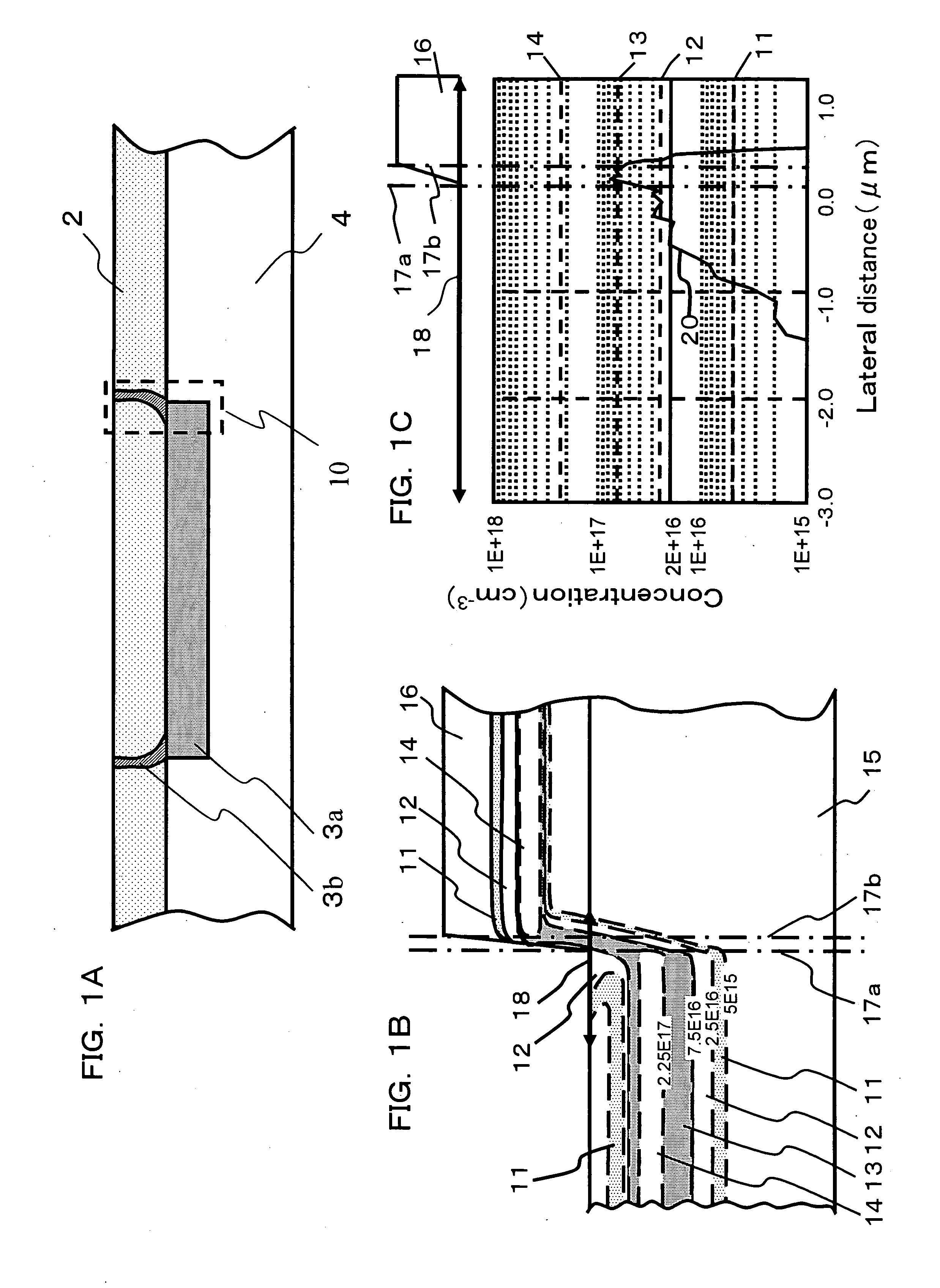
[0037] First, FIGS. 1A, 1B, and 1C are views for illustrating problems in detail of a related method for manufacturing a semiconductor device. In addition, FIG. 1A shows a P-type well region 2, an N-type well region 3a having a large doping depth, a region 3b which is implanted with an impurity passing through a resist, and a P-type semiconductor substrate 4, and a region 10 corresponding to that shown in FIG. 1B.

[0038] In addition, FIG. 1B shows a cross-sectional view of a semiconductor substrate 15 and a resist 16, and in the figure, there are shown isoconcentration lines 11, 12, 13, and 14 indicating concentrations of 5×10¹⁵ / cm3, 2.5×1...

example 2

[0069] Example 2 will be described with reference to FIGS. 5A to 5D, 6A to 6D, and 7A to 7D.

[0070] As shown in the above figures, Example 2 is an example relating to a method for manufacturing a semiconductor device in which there are formed a well region having a predetermined depth from a surface of a semiconductor substrate, one impurity region formed in the semiconductor substrate from the bottom portion of the above well region in the depth direction of the substrate, and a semiconductor element formed in the well region and in a boundary area of said one impurity region when viewed in plan.

[0071]FIGS. 5A to 5D are views for illustrating a method for manufacturing a semiconductor device, according to Example 2. In the manufacturing method described above, when a P-type well region or an N-type well region formed in the semiconductor substrate from the surface thereof, and an active element formed in the P-type well region or the N-type well region and in the boundary area of ...

example 3

[0091] With reference to FIGS. 8A to 8C, 9A and 9B, 10A to 10D, 11A to 11D, 12A to 12D, and 13A to 13D, Example 3 will be described. Example 3 is an example relating to a method for manufacturing a semiconductor device in which a triple well structure is formed and CMOS transistors are provided in this triple well, and in this example, one impurity region forming a triple well structure is formed by high-energy ion implantation of an impurity.

[0092] First, with reference to FIGS. 8A, 8B, and 8C, problems of a related method for manufacturing a semiconductor device will be described in detail. FIG. 8A shows an N-type well region 80 having a small doping depth, a P-type well region 81a forming a triple well structure, a P-type well region 81b not forming a triple well structure, an N-type well region 82a having a large doping depth, a region 82b which is implanted with an impurity passing through a resist, a P-type semiconductor substrate 83, a gate electrode and a channel region 84 ...


PUM


Abstract

The present invention provides a method for manufacturing a semiconductor device which includes a step of forming one optional impurity region in a semiconductor substrate at a place apart from the surface thereof, and in the method described above, ion implantation is performed a plurality of times while the position of an end portion of a mask pattern used for ion implantation is changed.

Description

BACKGROUND OF THE INVENTION [0001] 1. Field of the Invention [0002] The present invention relates to a method for manufacturing a semiconductor device, and more particularly, relates to a method for manufacturing a semiconductor device in which variation in properties of an element is suppressed which is formed in the vicinity of a semiconductor surface and also in a boundary area of an impurity region formed in a semiconductor substrate at a place apart from the surface thereof. [0003] 2. Description of the Related Art [0004] In recent years, high-energy ion implantation has been practically used; hence, by impurity ion implantation in combination with short period heat treatment, an impurity region can be formed in a semiconductor substrate at a place apart from a surface thereof. [0005] For example, in a semiconductor device incorporating a large scale integration (LSI) circuit, when a triple well structure is employed in which a P-type well region is surrounded by an N-type well...

Claims


Application Information

Patent Timeline
Patent Type & Authority Applications(United States)
IPC IPC(8): H01L21/336
CPCH01L21/26513H01L29/78H01L27/0928H01L21/823892
Inventor TANAKA, TAKUJI
Owner FUJITSU SEMICON LTD
Why Eureka
Try Eureka