

Alignment mark and method of forming the same
- Summary
- Abstract
- Description
- Claims
- Application Information
AI Technical Summary
Benefits of technology
Problems solved by technology
Method used
Image

Examples
first embodiment
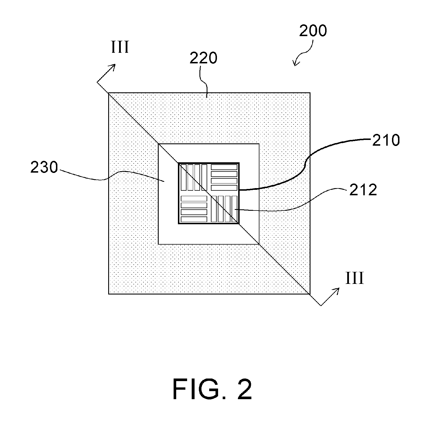
[0028]FIG. 2 is a top view illustrating an alignment mark 200 for a first embodiment for the present invention.
[0029] Referring to FIG. 2, the alignment mark 200 includes a mark portion 210. And the mark portion 210 has a plurality of notches 212. In addition, each notch 212 can be aligned in different directions. Furthermore, a trench structure 220 is surrounding the outside of the mark portion 210. And in between the trench structure 220 and the mark portion 210, lies a distance 230. In particularly, as the depth of the trench structure 220 becomes larger than that for each notch 212, the width for the trench structure 220 also becomes larger than that for each notch 212. The residue on the notch 212 can be removed by erosion effect caused by the trench structure 220 during processing period. The depth of the notch 212 is, for example, between 1200 angstroms to 1400 angstroms. Or it can vary according to the device dimensional changes. Furthermore, the aforementioned trench struct...
second embodiment
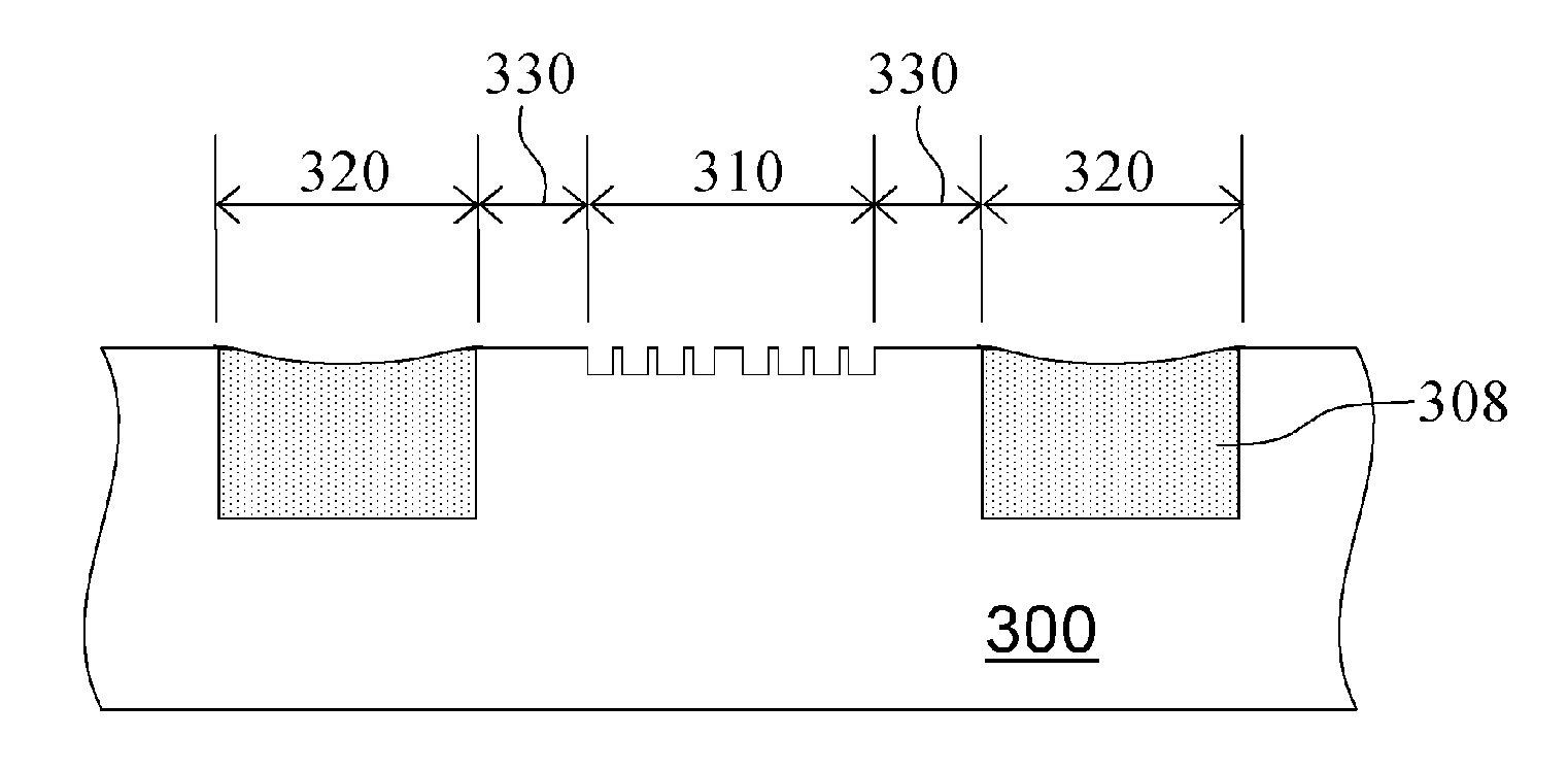
[0030]FIG. 3A to FIG. 3E are cross-sectional views illustrating the fabrication process for the alignment mark in the present invention. And they can also be cross referenced to the line III-III′ of FIG. 2.
[0031] Referring to FIG. 3A, first a substrate 300 is provided. And the substrate 300 has a mark area 310 and a trench area 320 in advance, in which the trench area 320 surrounds the mark area 310 and maintains a distance 330 between with the mark area 310. Later, a plurality of notches 312 is formed on the surface of the substrate 300 in the mark area 310. Afterwards, a pad layer (not illustrated) can be formed on the substrate 300 surface. Furthermore, the aforementioned substrate 300 can further include a shallow trench isolation area (not illustrated) for forming shallow trench isolation structure (STI). Because the fabrication process for the shallow trench isolation structure can be done using the conventional technology as reference; therefore, the fabrication process for f...
PUM
| Property | Measurement | Unit |
|---|---|---|
| Distance | aaaaa | aaaaa |
| Distance | aaaaa | aaaaa |
| Thickness | aaaaa | aaaaa |
Abstract
Description
Claims
Application Information