Eureka AIR delivers breakthrough ideas for toughest innovation challenges, trusted by R&D personnel around the world.

Method of positioning problem regions covered with indoor wireless network

Active Publication Date: 2016-11-17
RANPLAN WIRELESS NETWORK DESIGN
View PDF2 Cites 31 Cited by
  • Summary
  • Abstract
  • Description
  • Claims
  • Application Information

AI Technical Summary

Benefits of technology

The present invention provides a method for establishing a wireless fingerprint database using different methods such as manual field measurements, propagation model prediction, or small amount of measurements and large amount of prediction. It also allows for determining if a user equipment (UE) is from indoors or outdoors and applicable to various mobile communication networks. The invention utilizes MRs collected from the network side and does not require additional testing equipment or manual field measurements, resulting in cost advantages. The combined use of location information and MRs from the UE allows for more accurate identification of problem network areas. Overall, the invention provides a reliable and efficient solution for wireless fingerprint database development and utilization.

Problems solved by technology

Indoor wireless communication networks become more complex, 2G / 3G / LTE / WiFi and other network standards coexist, so upgrading and maintenance of existing complex indoor wireless networks and quickly positioning indoor blind coverage areas and problem devices become increasingly difficult.
Traditional indoor wireless network maintenance and upgrading methods, mainly based on customer complaints and field measurements by maintenance personnel to find blind coverage areas and problem devices, are not only time-consuming, but also incompetent to monitor the running states of indoor wireless networks in real time.
However, the wireless measurement report MR only records the problem cell and does not record the specific location thereof.
When the UE receives wireless signals from different transmitting antennas of the same indoor subsystem, these signals are from the same cell if seen from the network side, which brings new problems for locating blind coverage areas and problem devices of an indoor subsystem using the wireless measurement report MR.

Method used


Image

  • Method of positioning problem regions covered with indoor wireless network
  • Method of positioning problem regions covered with indoor wireless network
  • Method of positioning problem regions covered with indoor wireless network

Examples


Embodiment Construction

[0085]Hereinafter the invention is further described with reference to accompanying figures and embodiments.

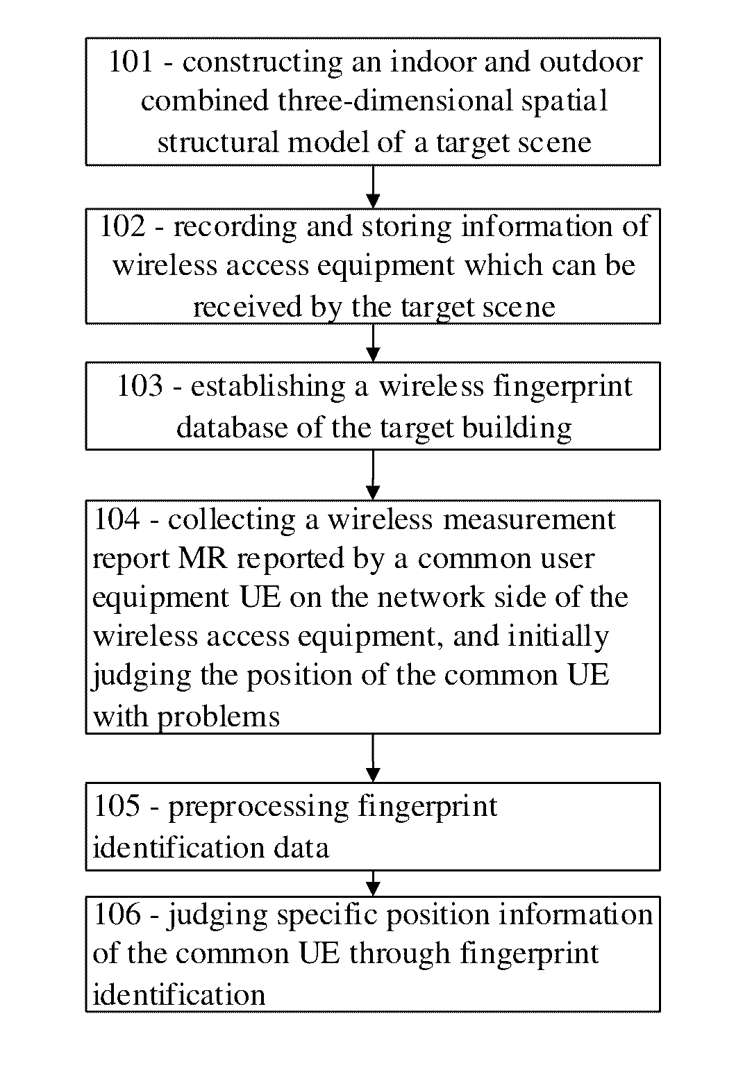
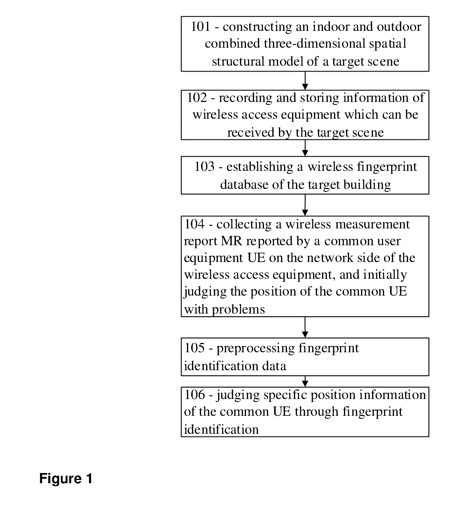
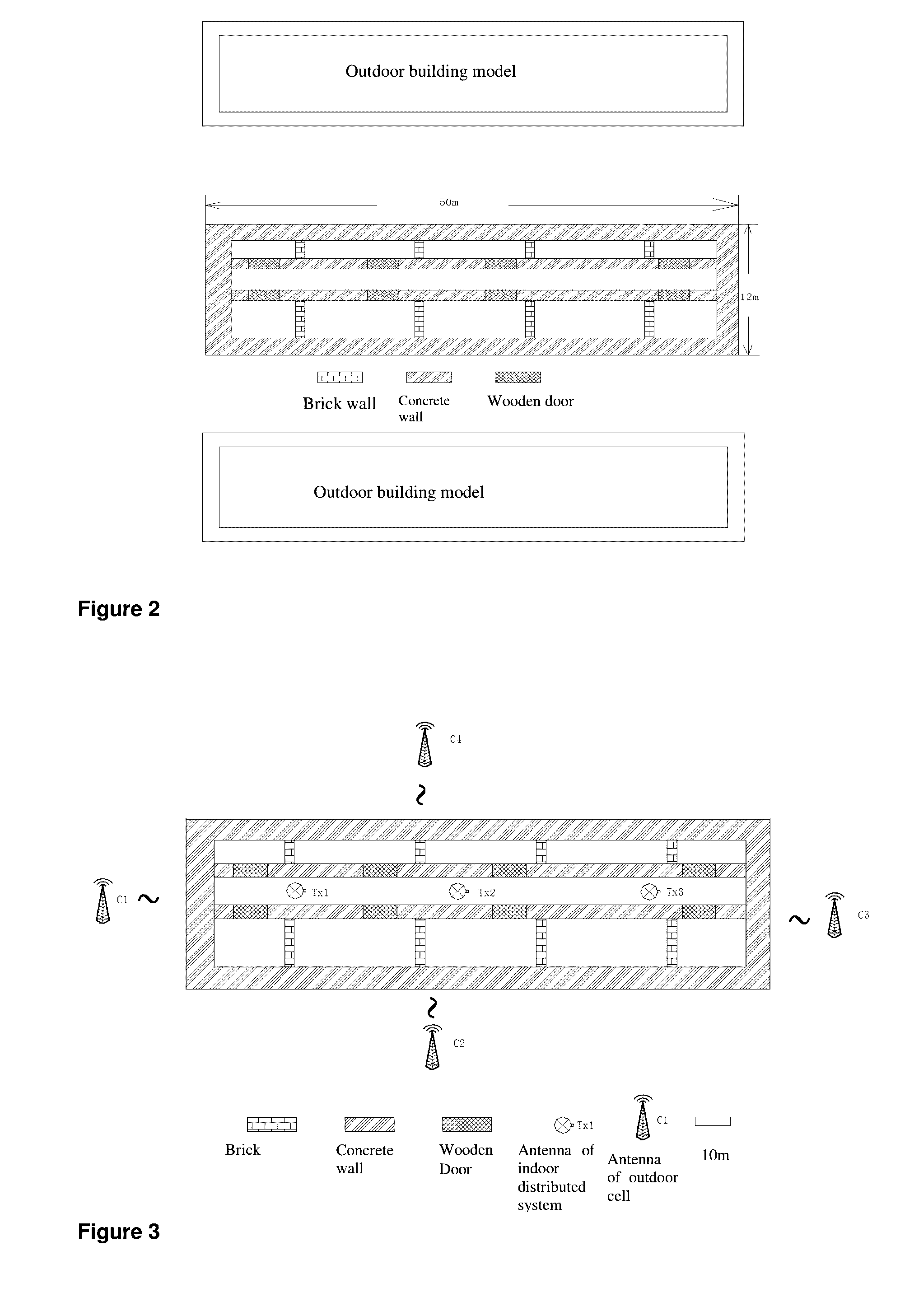
[0086]A method for method of positioning problem regions covered with an indoor wireless network according to the present invention is used for positioning blind coverage areas and problem devices of an indoor distributed system network within a target building. The five-floored target building has the same structure at each floor. A WCDMA network is established in the building. The WCDMA network covers the building through an indoor distributed system. The WCDMA network outside the target building is covered by outdoor macro base stations. The indoor distributed system and the outdoor macro base stations belong to different cells.

[0087]It needs to be noted that the present invention is not limited to WCDMA networks, and can also be applied to a combination of other wireless wide area networks.

[0088]As shown in FIG. 1, a method of positioning problem regions covered with an in...


PUM


Abstract

Method of positioning blind coverage regions in an indoor wireless network. The method comprises the following steps: constructing an indoor and outdoor combined three-dimensional spatial structural model of a target scene; recording and storing information of wireless access equipment which can be received by the target scene, both from the indoor wireless network and from an outdoor (e.g., cellular) network with overlapping coverage; establishing a wireless fingerprint database of the target building covering both the indoor and the outdoor wireless networks; when loss of coverage is detected, the UE handing over to the outdoor network to transmit a measurement report from which the outdoor network can derive the UE's position (e.g., through triangulation); deriving the UE's position in the indoor area by superimposing the obtained information on the fingerprinting database (by analyzing only those cell-Id's that appear on the MR) and interpolating the result (mean square error); if the obtained position is covered by the fingerprinting database (i.e., it is in the indoor area), determining that the position corresponds to a blind coverage area inside the indoor wireless area; otherwise, assuming that the UE has left the building and a normal handover has taken place.

Description

TECHNICAL FIELD[0001]The present invention relates to a method of positioning problem regions covered with an indoor wireless network, belonging to the field of maintenance of an indoor wireless network for mobile communication.BACKGROUND OF THE INVENTION[0002]In a voice-based communication 2G era, outdoor macro base stations will be able to realize indoor coverage. As wireless communication technologies develop and indoor data services increase, indoor wireless signals become increasingly important. An indoor distributed system becomes a main form to realize indoor wireless network coverage. Indoor wireless communication networks become more complex, 2G / 3G / LTE / WiFi and other network standards coexist, so upgrading and maintenance of existing complex indoor wireless networks and quickly positioning indoor blind coverage areas and problem devices become increasingly difficult. Traditional indoor wireless network maintenance and upgrading methods, mainly based on customer complaints a...

Claims


Application Information

Patent Timeline
IPC IPC(8): H04W24/08H04W36/14H04W64/00G06F17/30G06T17/05G06T15/06G06F17/50G06F17/11H04W16/20H04W36/00
CPCH04W24/08H04W16/20H04W36/14H04W64/00H04W36/0061G06T2210/61G06T15/06G06F17/5004G06F17/11G06F17/30589H04W84/12G06T17/05H04W24/02H04W24/10H04W36/04G06F16/282G01S5/02521G06F30/13
Inventor ZHANG, JIEQIN, CHUNXIAWU, JOYCESONG, HUI
Owner RANPLAN WIRELESS NETWORK DESIGN
Why Eureka
Eureka Blog
Learn More