V-belt continuously variable transmission and straddle-type vehicle

a technology of continuously variable transmission and v-belt, which is applied in mechanical equipment, transportation and packaging, and gearing, etc., can solve the problems of deteriorating durability, speed actually decreasing, and delay in response of sheave drive mechanism, and achieve high durability

Active Publication Date: 2007-03-08
YAMAHA MOTOR CO LTD
View PDF12 Cites 8 Cited by
  • Summary
  • Abstract
  • Description
  • Claims
  • Application Information

AI Technical Summary

Benefits of technology

[0019] In order to overcome the problems described above, preferred embodiments of the present invention provide a V-belt CVT having

Problems solved by technology

However, when the road on which the vehicle is running turns from a flat road to a climbing road, for example, the sheave drive mechanism of the centrifugal type does not perform a groove width control operation (specifically, a speed change operation) responsively according to changes in the road condition, irrespective of the intention of the rider, until the engine speed has actually decreased because of the increased load from the road.
That is, the sheave drive mechanism has a problem of delayed response.
However, foreign matter entering the ball screw mechanism can damage the surfaces of the ball grooves and balls, deteriorating its durability.
However, different from scooter-type motorcycles, ATVs are often used off-road and are thus at a high risk of water entering the transmission case through the air inlet and outlet ports for cooling purposes when running over deep puddles, down ri

Method used


Image

  • V-belt continuously variable transmission and straddle-type vehicle
  • V-belt continuously variable transmission and straddle-type vehicle
  • V-belt continuously variable transmission and straddle-type vehicle

Examples


Embodiment Construction

[0037] A preferred embodiment of a V-belt continuously variable transmission (CVT) and a straddle-type vehicle according to another preferred embodiment of the present invention will hereinafter be described in detail with reference to the drawings.

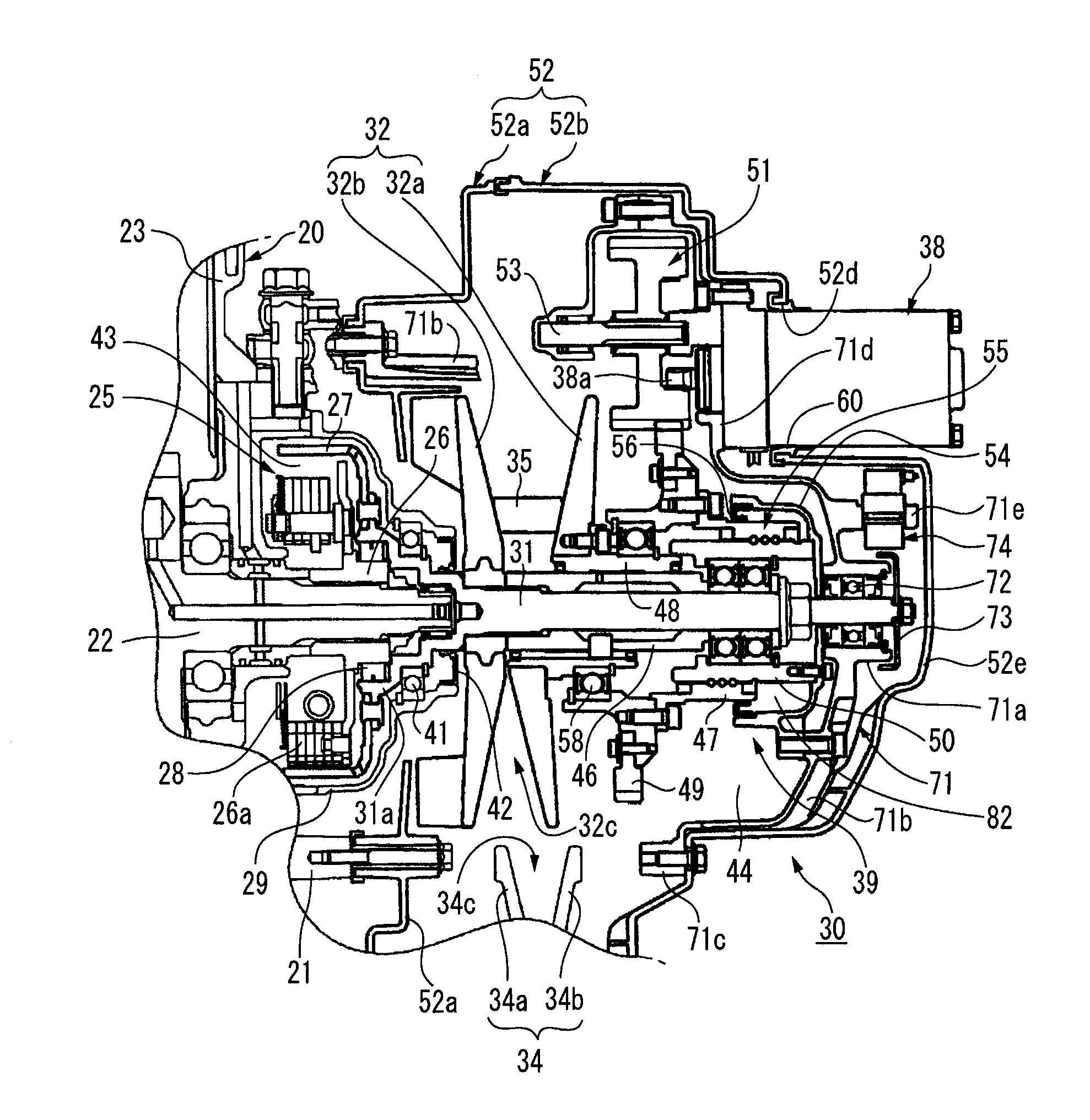
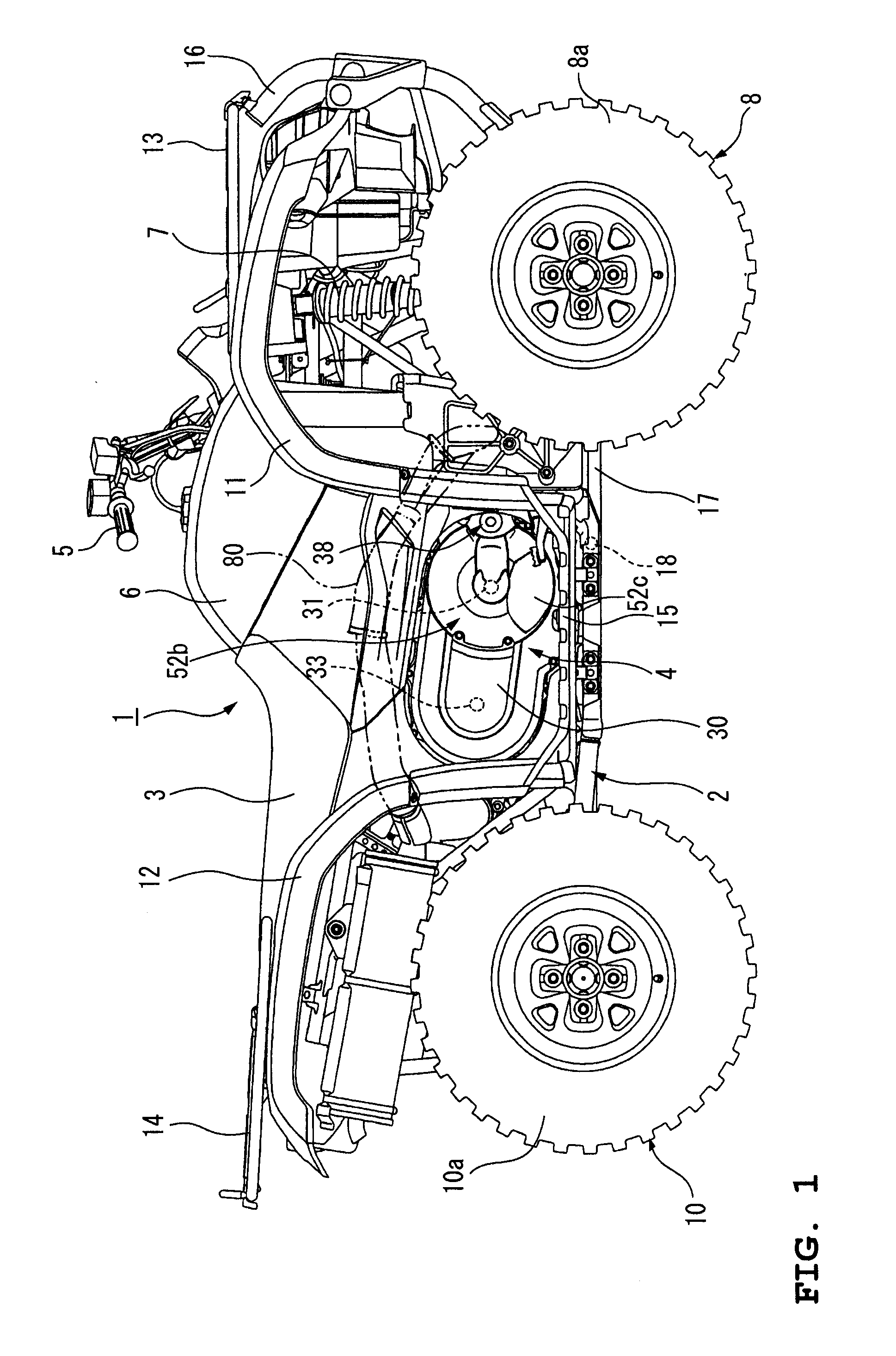
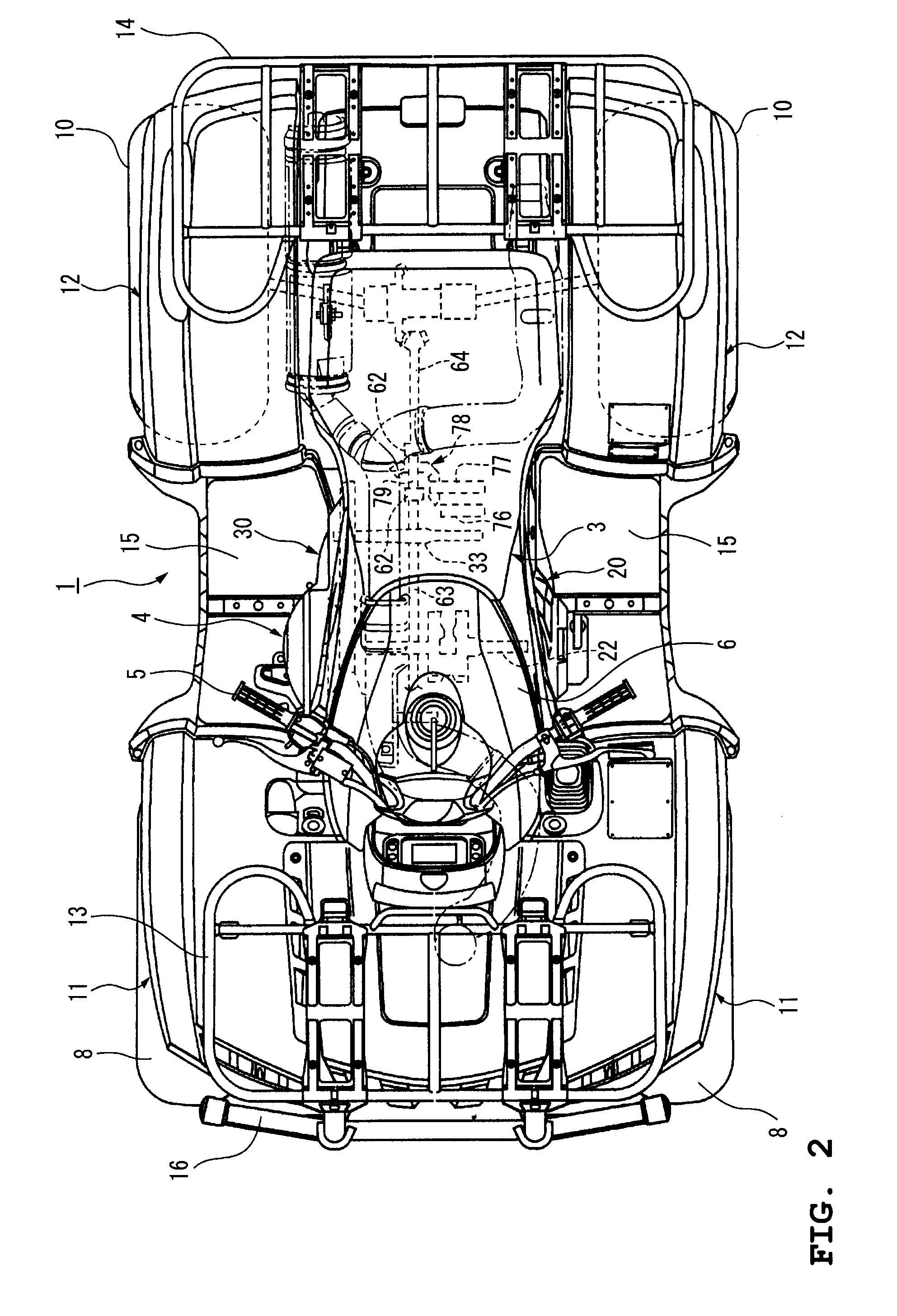
[0038]FIGS. 1 through 5 illustrate a straddle-type vehicle incorporating a V-belt CVT according to a preferred embodiment of the present invention. FIG. 1 is a right side view of the straddle-type vehicle incorporating a power unit in which the V-belt CVT according to the present preferred embodiment of the present invention is assembled to an engine. FIG. 2 is a plan view of the straddle-type vehicle shown in FIG. 1. FIG. 3 is a right side view of the power unit mounted in the straddle-type vehicle shown in FIG. 1 with a cover of the V-belt CVT removed. FIG. 4 is a sectional view taken along the line A-A of FIG. 3. FIG. 5 is a sectional view taken along the line B-B of FIG. 3. In this specification, “left” and “right” refer to the left ...


PUM


Abstract

In a V-belt continuously variable transmission (CVT), a sheave drive mechanism includes a movable tube coupled to a movable sheave half of a primary sheave so as to be rotatable with respect thereto and axially movable together therewith, a fixed tube disposed internally of and coaxially with the movable tube, and a ball screw mechanism provided between the fixed tube and the movable tube. The sheave drive mechanism further includes an outer peripheral wall arranged to cover the area from a fixed end of the fixed tube to the outer periphery of the movable tube, an oil seal provided between the movable tube and the outer peripheral wall to seal an internal space for enclosing the working surface of the ball screw mechanism, and a communication path for communication between the internal space and the outside of the outer peripheral wall. The V-belt (CVT) has a smooth feed operation of the ball screw mechanism in the sheave drive mechanism and has a high durability attained by waterproofing.

Description

BACKGROUND OF THE INVENTION [0001] 1. Field of the Invention [0002] The present invention relates to a V-belt continuously variable transmission (CVT) for transmitting a driving force of an engine to a driving wheel, and a straddle-type vehicle having the V-belt CVT disposed below a seat of the vehicle. [0003] 2. Description of the Related Art [0004] Recently, there is an increasing demand for straddle-type vehicles called “ATVs (all-terrain vehicles).”[0005] Also, there have been proposed various types of ATVs in which four wheels are provided, each wheel having a wide and low-pressure balloon tire or the like on the left and right sides of the front and rear ends of a body frame, the upper portion of the body frame is provided with steering handlebars, a fuel tank, and a straddle-type seat, arranged sequentially from the front wheel side to the rear wheel side, and a V-belt CVT disposed below the seat for transmitting a driving force of an engine to the driving wheels (see JP-A-20...

Claims


Application Information

Patent Timeline
IPC IPC(8): F16H61/00F16H9/12B60K17/08B62M9/04B62M9/08F16H9/18
CPCF16H9/18F16H25/2204Y10T74/1946F16H63/067F16H55/56
Inventor MOCHIZUKI, SHIGEHIROIZUMI, KAZUHIKO
Owner YAMAHA MOTOR CO LTD
Why Eureka
Try Eureka