
Color conversion apparatus and method

a color conversion and apparatus technology, applied in the field of color conversion using a table, can solve the problems of inability to ensure correct color reproduction, adversely affect tonability, and the probability of discontinuity on the boundary surface to become problematic, so as to enhance color reproducibility, maintain tonability, and improve accuracy

Inactive Publication Date: 2007-03-15
CANON KK
View PDF8 Cites 11 Cited by
  • Summary
  • Abstract
  • Description
  • Claims
  • Application Information

AI Technical Summary

Benefits of technology

[0020] According to another aspect of the present invention, a nonlinear interpolation capable of approximating characteristics of a device with good accuracy is employed in a color estimation algorithm. Also, a linear interpolation is applied only on an area having a high degree of linearity, for example, an area in the vicinity of a gray in a color space. Thus, an exemplary embodiment can solve a problem of a distortion of a gray axis in a result of interpolation using only a nonlinear interpolation method. Furthermore, an exemplary embodiment can enhance color reproducibility over the entire color space by using a nonlinear interpolation method while maintaining tonability, and also can enhance color reproducibility of a gray axis by using a linear interpolation method while maintaining tonability.
[0021] According to another aspect of the present invention, color reproducibility of an optionally designated area, for example, a flesh area or an azure area in a color space can be enhanced by setting a fine grid point interval in a part of the color space or changing an interpolation method with parts thereof, while maintaining performance and tonability over the entire color space.

Problems solved by technology

Under an illuminant based on another reference, correct color reproduction is not assured.
However, the method discussed in Japanese Patent Application Laid-Open No. 10-136216 has a problem in that discontinuity may occur on a boundary surface between a specific unit cube and the outside thereof and may adversely affect tonability.
Thus, the discontinuity on the boundary surface is unlikely to become problematic.
However, in a case where the input values are floating point values, tonability is highly likely to deteriorate.
Thus, this method cannot successfully be applied to this case.

Method used


Image

  • Color conversion apparatus and method
  • Color conversion apparatus and method
  • Color conversion apparatus and method

Examples


Embodiment Construction

[0044] Exemplary embodiments of the invention will now be described in detail below with reference to the accompanying drawings.

[0045] Color Matching Process Using Color Appearance Model

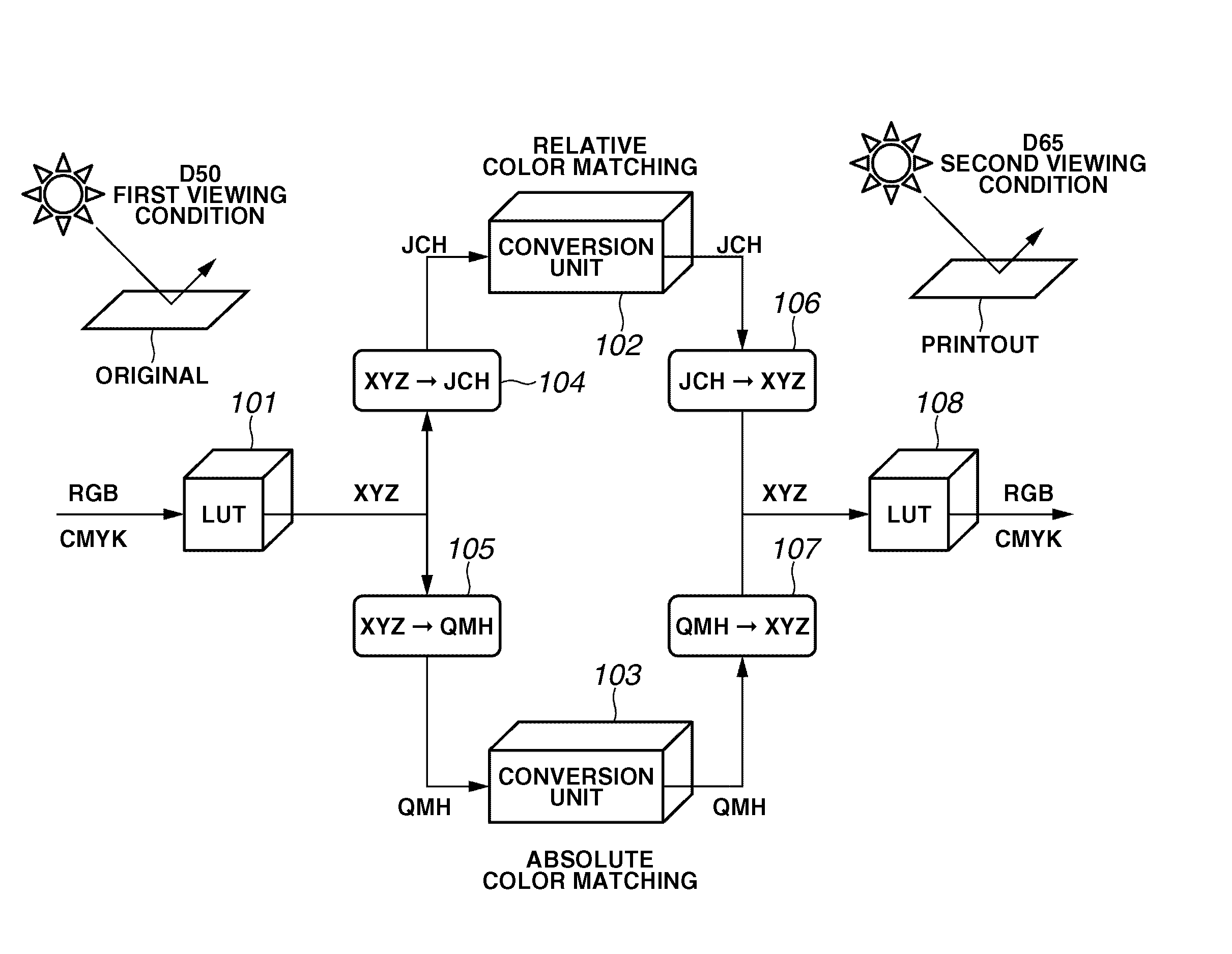
[0046]FIG. 1 is a conceptual diagram illustrating a color matching process using a color appearance model. As shown in FIG. 1, a conversion matrix or a conversion lookup table (LUT) 101 is used to convert an input-device-dependent color signal into device-independent color space data based on a white point reference for input-side ambient light. Color appearance model forward conversion units 104 and 105 convert an XYZ signal, which is output from the conversion LUT 101, into human color appearance color signals JCH and QMH according to input viewing conditions (a white point corresponding to a D50 illuminant, an illuminance level, and a state of ambient light), respectively. Color appearance model inverse conversion units 106 and 107 convert human color appearance color signals JCH and QMH into XY...


PUM


Abstract

A color conversion apparatus includes a plurality of color conversion units configured to perform color conversion using a conversion table with different algorithms, a weighting unit configured to set weightings applied to the plurality of color conversion units, and a mixing unit configured to mix a plurality of color conversion results obtained by the plurality of color conversion units using the weightings calculated by the weighting unit.

Description

BACKGROUND OF THE INVENTION [0001] 1. Field of the Invention [0002] The present invention relates to color conversion using a table. [0003] 2. Description of the Related Art [0004] Today, with development of computers, digital image data is very commonly distributed. Color matching is known as a technique of converting input image data to color signals suitable for devices, which are to be used, by taking differences in color representation among the devices into account. [0005] A conventional color matching method is described below by referring to a conceptual diagram illustrated in FIG. 21. Input data (RGB-data) is converted by an input profile 101 into XYZ data in a device-independent color space. Because an output device cannot reproduce colors that are outside a color gamut of the output device, gamut mapping is performed on the XYZ data, into which the input data has been converted, to map the XYZ data onto color data which is within the color gamut of the output device. The ...

Claims


Application Information

Patent Timeline
Patent Type & Authority Applications(United States)
IPC IPC(8): H04N1/60
CPCH04N1/6016
Inventor KODAMA, YOICHI
Owner CANON KK
Learn More