
Multi-function printer

a multi-function printer and printer technology, applied in the direction of digital output to print units, instruments, visual presentations, etc., can solve the problems of increasing the standby power consumption of the facsimile machine, the inability to forecast the arrival time of the facsimile, and the average power consumption of the facsimile, so as to reduce the power consumption of the multi-function printer, reduce the power consumption, and improve the operability

Inactive Publication Date: 2007-03-15
SHARP KK
View PDF13 Cites 22 Cited by
  • Summary
  • Abstract
  • Description
  • Claims
  • Application Information

AI Technical Summary

Benefits of technology

[0013] In consideration of the above-mentioned circumstances, an object of the present invention is to reduce power consumption in a multi-function printer which can be connected to an external device during standby. Especially, another object of the present invention is to reduce power consumption in a power saving mode according to a usage manner of the user in a multi-function printer which automatically switches between a normal power mode and a power saving mode. Still another object of the present invention is to provide a multi-function printer having good operability.
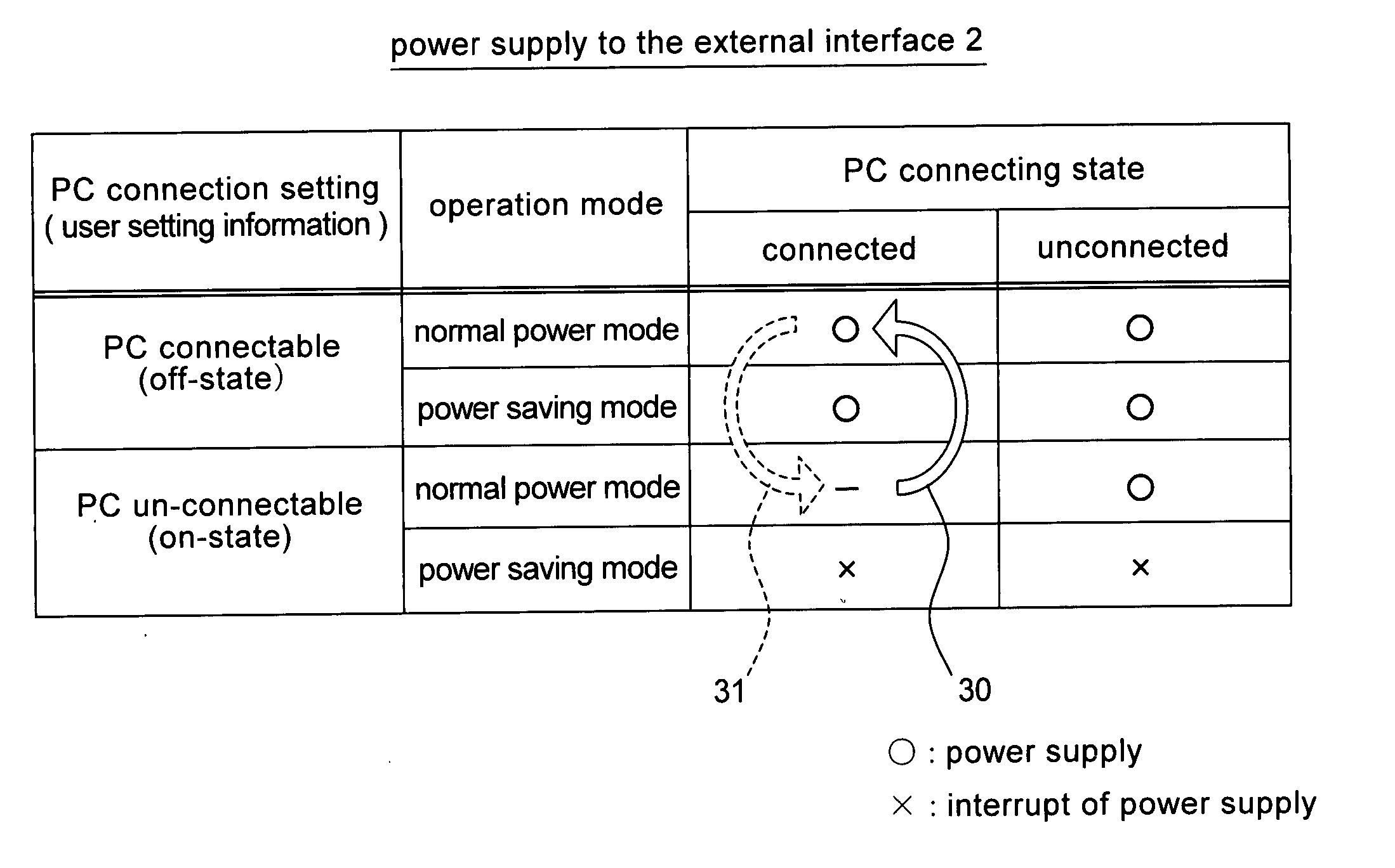
[0017] With such configuration, in the power saving mode for interrupting the power supply to the facsimile communication unit, the power supply to the external interface unit can be interrupted on the basis of the user setting information Therefore, according to the usage manner of the user, the power consumption in the power saving mode can be reduced.
[0019] With such configuration, on the basis of the detection result on the connecting state of the external device in the normal power mode, the power supply to the external interface unit in the subsequent power saving mode can be interrupted. Thus, according to the connecting state of the external device, power consumption in the power saving mode can be reduced.
[0021] With such configuration, even when the user setting information is set, if the connecting state of the external device is detected, the user setting information is automatically reset so that the power supply to the external interface unit in the subsequent power saving mode may not be interrupted. Therefore, even when the user does not change the user setting information, the multi-function printer can communicate with the external device in the power saving mode, thereby improving operability of the multi-function printer.
[0023] With such configuration, when the external device is connected, it is possible to prevent the user from setting the user setting information by mistake and prevent the user from wrongly operating so that communication with the external device cannot be performed in the power saving mode.
[0024] According to the present invention, it is possible to reduce power consumption in the multi-function printer which can be connected to the external device during standby. Especially in the multi-function printer having the normal power mode and the power saving mode, power consumption in the power saving mode can be reduced according to the usage manner of the user. Furthermore, a multi-function printer with good operability can be provided.

Problems solved by technology

Since facsimile reception is activated by arrival of the incoming signal from the other facsimile machine, time of facsimile reception cannot be forecasted on the arrival side.
Since the standby time is far longer than the facsimile reception time, average power consumption in the facsimile machine is greatly influenced by standby power consumption.
Thus, in the conventional general multi-function printer, power is supplied to the external interface unit at all times. As a result, even when the PC is not connected and the operating mode is the power saving mode, power is disadvantageously consumed in the external interface unit at any time, thereby increasing the standby power consumption of the facsimile machine.

Method used


Image

  • Multi-function printer
  • Multi-function printer
  • Multi-function printer

Examples


Embodiment Construction

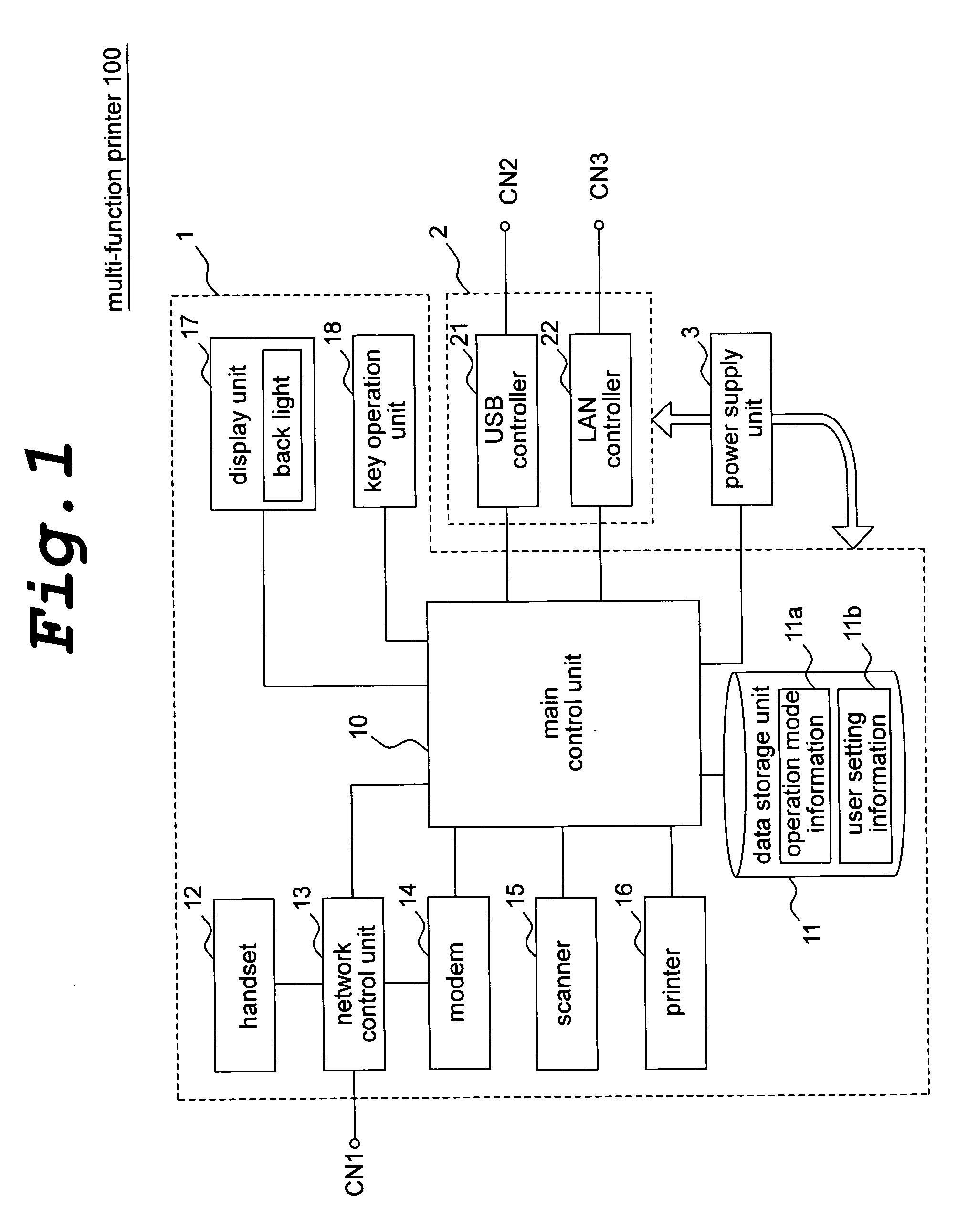
[0033]FIG. 1 is an interrupt diagram showing an example of configuration of a multi-function printer in accordance with an embodiment of the present invention. This multi-function printer 100 is composed of a facsimile main unit 1, an external interface unit 2 and a power supply unit 3.

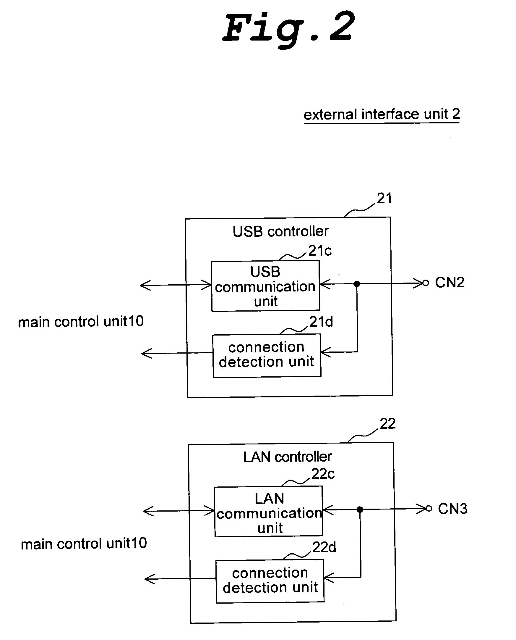
[0034] The facsimile main unit 1 is connected to the public communication line via a telephone line connector CN1 and can transmit / receive document information to / from the other facsimile machine not shown (facsimile transmission). The external interface unit 2 is an interface circuit connected to an information processing device such as a PC via a USB (Universal Serial Bus) connector CN2 or a LAN (Local Area Network) connector CN3. The power supply unit 3 is a power source circuit for supplying power to the facsimile main unit 1 and the external interface unit 2.

[0035] Given that the telephone line connector CN1 is connected to the telephone line, even if the USB connector CN2 or the LAN connector ...


PUM


Abstract

The present invention intends to reduce standby power consumption in a multi-function printer which can be connected to an external device. The multi-function printer has user setting information 11b which can be changed by a user and in a power saving mode, a power supply unit 3 interrupts a power supply to a modem 14, a scanner 15, a printer 16 and a back light of a display unit 17 and the like, and also interrupts a power supply to an external interface unit 2 on the basis of the user setting information 11b. On the basis of detection results of connection detection units 21d and 22d for detecting the connecting state to a PC 102, the user setting information 11b is automatically changed so that the power supply to the external interface unit 2 in the subsequent power saving mode may not be interrupted. During connection to the PC, a changing operation of the user setting information 11b by the user is restricted.

Description

BACKGROUND OF THE INVENTION [0001] 1. Field of the Invention [0002] The present invention relates to a multi-function printer, in particular, improvement in a multi-function printer which can be independently used as a facsimile machine and also can be used as peripheral equipment of the information processing device when being connected to the information processing device such as a personal computer. [0003] 2. Description of the Related Art [0004] Generally, a facsimile machine is composed of a modem unit for transmitting / receiving image information via a public communication line, a scanner unit for optically reading the image information from a paper medium and a printer unit for recording the image information on the paper medium. At the time of facsimile transmission, document information read from the paper medium by the scanner unit is transmitted to the public communication line through the modem unit. At the time of facsimile reception, document information received by the...

Claims


Application Information

Patent Timeline
IPC IPC(8): G06F3/12
CPCH04N1/00204H04N1/00885H04N1/00896H04N2201/3276H04N2201/0036H04N2201/0094H04N1/32106
Inventor HARUMICHI, TAMURA
Owner SHARP KK
Learn More