Illumination device and display device

a technology of illumination device and display device, which is applied in the direction of lighting and heating apparatus, planar/plate-like light guides, instruments, etc., can solve the problems of serious problems such as small leds when compared with illumination devices, and irregular illumination intensity and brightness. achieve the effect of being inexpensiv

Active Publication Date: 2007-03-15
HANNSTAR DISPLAY CORPORATION
View PDF8 Cites 50 Cited by
  • Summary
  • Abstract
  • Description
  • Claims
  • Application Information

AI Technical Summary

Benefits of technology

[0020] According to the present invention, an illumination device that uniformly distributes emitted light, is compact, and is inexpensive can be realized.

Problems solved by technology

However, LEDs are small when compared with illumination devices, and resemble point light sources.
For this reason, when a plurality of LEDS are used in the manufacture of an illumination device, irregularities in illumination intensity and brightness occur.
These irregularities in illumination intensity and brightness are a serious problem particularly when such an illumination device is used as the backlight of a liquid crystal display device.
However, when the LEDs are sorted, the cost of the device increases.
However, problems such as those described hereafter are presented in the above-described prior art.
Therefore, a plurality of light-guide bodies are needed when a plurality of point light sources are to be provided, inevitably increasing the cost.
Also, the light-guide body is disposed alongside the transparent substrate, and, as a result, the peripheral space inevitably expands when the number of light-guide bodies is increased.
However, in this configuration, the light emitted from the two point light sources cannot be mixed.
Therefore, when LEDs are used as the point light sources, irregularities caused by differences between the individual LEDs readily occur.
Additionally, because the light emitted from the point light sources cannot be mixed, RGB-emitting LEDs cannot be used as the light source.
However, when light emitted from a point light source (i.e., the left-side point light source) corresponding to a Fresnel lens that is adjacent to the opposite side of this region, as seen along the optical axis of the Fresnel lens, is incident on the abovementioned region of the Fresnel lenses, the light cannot be directed in a prescribed direction.
Also, even the light incident from point light sources disposed in positions further away cannot be directed in a prescribed direction.
For this reason, there is a limit to the light mixing effect, and, while light emitted from, e.g., two mutually adjacent point light sources can be partially mixed, light emitted from three point light sources cannot be uniformly mixed.
Consequently, white light is difficult to produce when using RGB-emitting LEDs as the light sources.
Additionally, as shown in FIG. 14 of publicly known document 4, only an intensity of about 70% of intensity along the optical axis can be achieved in the peripheral areas of the unit Fresnel lenses, and uniformity is inadequate.

Method used


Image

  • Illumination device and display device
  • Illumination device and display device
  • Illumination device and display device

Examples


example 1

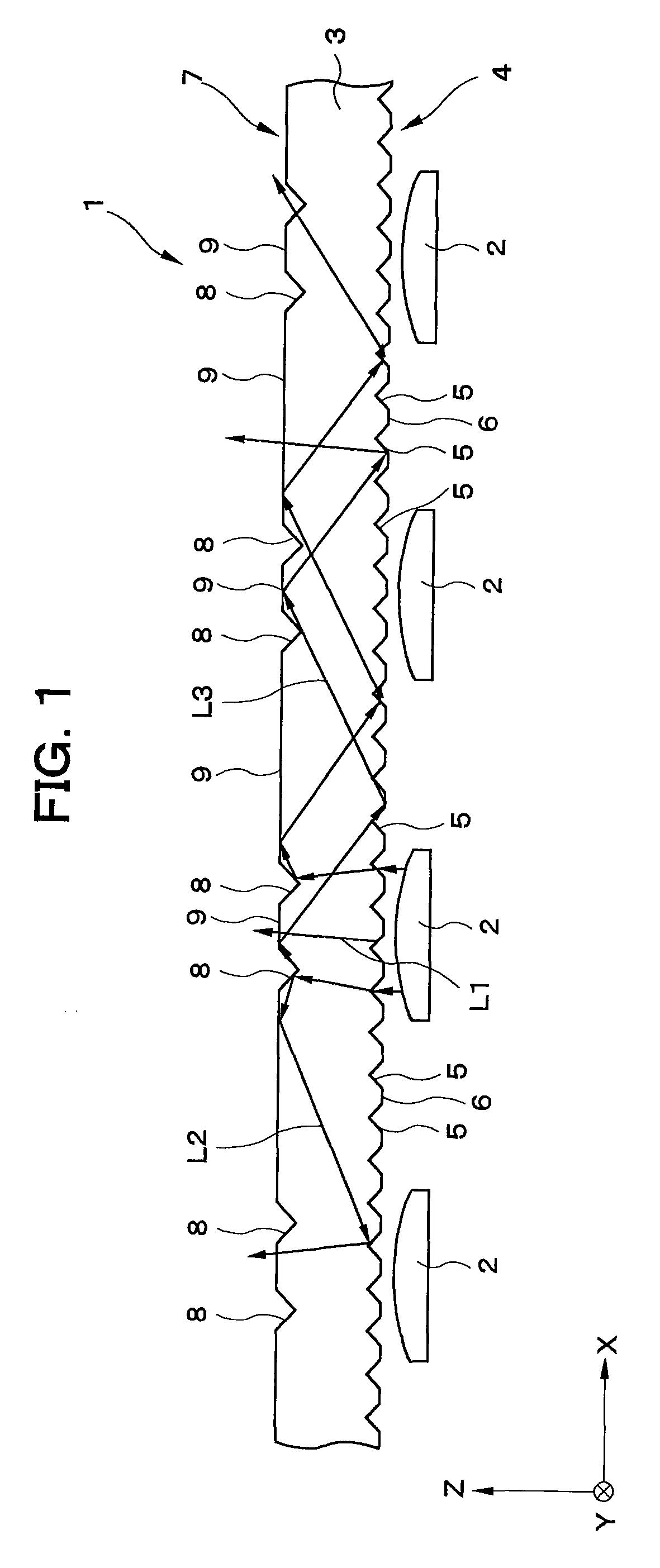
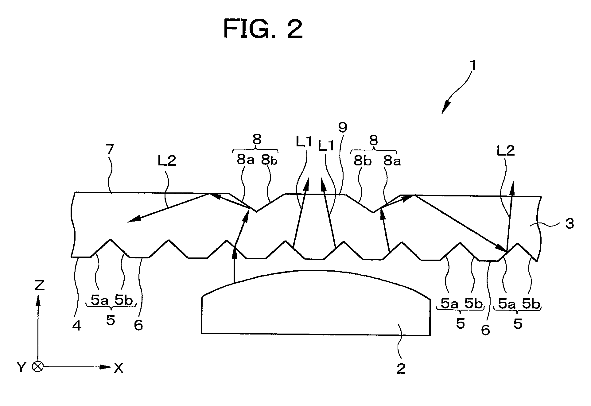
[0131] Examples of the present invention are described below. Example 1 is first described. FIG. 25 is an optical model diagram showing an illumination device according to example 1; FIG. 26 is an enlarged view of section A in FIG. 25; FIG. 27 is an enlarged view of section B in FIG. 25; FIG. 28 is an enlarged view of section C in FIG. 25; and FIG. 29 is an enlarged view of section D in FIG. 25. The dimensions of each part are shown in FIGS. 26 through 29, and the unit of measurement is millimeter (mm).

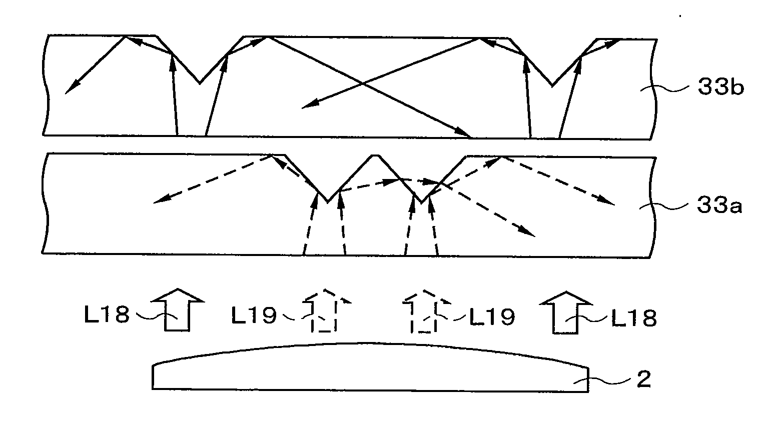
[0132] In Example 1, nine white LEDs 52 were disposed at intervals of 9 mm, as shown in FIG. 25. The angle at which light was emitted by the white LEDs 52 was ±10 degrees, and the LEDs 52 had a disc-shaped outer contour having a diameter of 5 mm. Two light-guide plates 53a and 53b were disposed on the light-emitting side of the white LEDs 52. A reflecting plate (not shown) was additionally disposed in portions that excluded the light-emitting side of the light-guide plate 53b so as t...

example 2

[0136] An example 2 is next described. FIG. 31 is an optical model diagram of an illumination device according to example 2; FIG. 32 is an enlarged view showing section A in FIG. 31; FIG. 33 is an enlarged view showing section B in FIG. 31; FIG. 34 is an enlarged view showing section C in FIG. 31; FIG. 35 is an enlarged view showing section D in FIG. 31; FIG. 36 is an enlarged view showing section E in FIG. 31; and FIG. 37 is an enlarged view showing section F in FIG. 31. The dimensions of each part are shown in FIGS. 32 through 37, and the unit of measurement is millimeter (mm).

[0137] In example 2, nine white LEDs 62 were disposed at intervals of 8.75 mm, as shown in FIG. 35. The angle at which light was emitted by the white LEDs 62 was ±10 degrees, and the LEDs 62 had a disc-shaped outer contour having a diameter of 5 mm. Two light-guide plates 63a and 63b were disposed on the light-emitting side of the white LEDs 62. A reflecting plate (not shown) was additionally disposed in po...

example 3

[0145] An example 3 is next described. FIG. 39 is an optical model diagram showing an illumination device according to example 3; FIG. 40 is an enlarged view showing section A in FIG. 39; FIG. 41 is an enlarged view showing section B in FIG. 39; and FIG. 42 is an enlarged view showing section C in FIG. 39. The dimensions of each part are shown in FIGS. 40 through 42, and the unit of measurement is millimeter (mm).

[0146] In example 3, three each of a red LED 72R, a green LED 72G, and a blue LED (not shown), for a total of 9 LEDS, were arrayed in an order of “BGRBGRBGR,” as shown in FIG. 39. The array interval of the LEDs was 8.75 mm. The angle at which light was emitted by the LEDs 52 was ±10 degrees, and the LEDs 52 had a disc-shaped outer contour having a diameter of 5 mm. A light-guide plate 73a was disposed on the light-emitting side of the LEDs; and a light-guide plate 63b was disposed on the light-emitting side of the light-guide plate 73a. The light-guide plate 63b was the sa...


PUM


Abstract

A plurality of LEDs are arrayed in the X-direction, and a light-guide plate is provided facing the LEDs. A plurality of prisms extending in the Y-direction are formed on a light-receiving surface of the light-guide plate. A plurality of prisms are additionally formed on a light-emitting surface of the light-guide plate. Light emitted from the LED is thereby divided into a plurality of light beams by the prisms, and a portion of the light is condensed toward the prisms. Light that is condensed toward the prisms is divided in a plurality of directions and transmitted in the light-guide plate. When the light reaches another prism, the light is reflected by the prism and emitted from the light emitting surface.

Description

BACKGROUND OF THE INVENTION [0001] 1. Field of the Invention [0002] The present invention relates to an illumination device comprising a point light source that diffuses and emits light emitted from the point light source, and to a display device comprising this illumination device. [0003] 2. Description of the Related Art [0004] In recent years, the use of LEDs (light emitting diodes) as illumination devices for in-home use and light sources for backlights of liquid crystal display devices in place of fluorescent lamps and cold-cathode fluorescent lamps (CCFL) has been actively examined. LEDs are more environmentally friendly when compared with CCFLs and the like, and have the potential to reduce energy consumption in the future. However, LEDs are small when compared with illumination devices, and resemble point light sources. Therefore, the light emitted from an LED must be linearly or in a plane diffused. Additionally, the amount of light emitted per LED is smaller than the amoun...

Claims


Application Information

Patent Timeline
Patent Type & Authority Applications(United States)
IPC IPC(8): G09F13/04
CPCG02B5/045G02B6/0016G09F13/04G02B6/0038G02F1/133606G02B6/0018
Inventor SAITOH, GOROHIMAI, MASAO
Owner HANNSTAR DISPLAY CORPORATION
Why Eureka
Try Eureka