Backlight unit

a backlight unit and backlight technology, applied in lighting support devices, lighting and heating apparatuses, instruments, etc., can solve the problems of increasing the size of the frame outside the display area of the inability to uniformly illuminate the liquid crystal panel, and the display quality decreases, so as to improve the uniformity of luminance within the surface, narrow display frame, and thin design

Active Publication Date: 2007-03-15
NEC LCD TECH CORP
View PDF6 Cites 23 Cited by
  • Summary
  • Abstract
  • Description
  • Claims
  • Application Information

AI Technical Summary

Benefits of technology

[0017] According to a backlight unit based on the present invention, it is possible to improve the uniformity of luminance within a surface illuminated by the backlight while realizing a narrow display frame, thin design and low manufacturing cost due to narrower frame breadth. This is because a reflecting member does not have an even reflectance, because the reflecting member is divided into at least end regions near the electrode or near the end lamp and a middle region on the middle side nearer to the middle than the end regions, and because the reflectance in the end regions is made higher than that of the middle region. As a result of this, a decrease in luminance which occurs due to the characteristics of the lamp and the arrangement of the lamp can be positively suppressed without an increase in the size of the frame breadth, an increase in thickness and a rise in price.

Problems solved by technology

As a result, even when the diffuser 4 is arranged, it is impossible to uniformly illuminate the liquid crystal panel, there by posing the problem that display quality decreases.
As a result, this poses the problem that the size of a frame outside the display area of the liquid crystal panel increases.
In the latter construction, because the reflecting section is worked in wave form, the construction becomes complicated and the manufacturing cost increases.
Furthermore, the uneven construction of the reflecting section poses the problem that the thickness of the backlight unit increases inevitably.
In addition to the problem of a decrease in luminance in the longitudinal direction of the lamp 5, there is another problem that luminance decreases in the arrangement direction of the lamp 5 arranged in multiple numbers.
However, in a case where the spacing between the end lamp and the inclined surface is large, a decrease in luminance cannot be sufficiently suppressed by the reflection from the inclined surface alone.

Method used


Image

  • Backlight unit
  • Backlight unit
  • Backlight unit

Examples


first exemplary embodiment

[0056] First, the first exemplary embodiment of the present invention will be described. FIG. 3 is a perspective view which shows the construction of a backlight unit according to the first exemplary embodiment of the present invention in an exploded condition. FIG. 4A is a plan view which shows the positional relationship of main members of the backlight unit according to the first exemplary embodiment of the present invention. FIG. 4B is a sectional view which schematically shows the section along the line IVB-IVB in FIG. 4A as viewed from the direction of the arrow. FIG. 5 is a plan view which shows the construction of a reflecting member according to the first exemplary embodiment of the present invention.

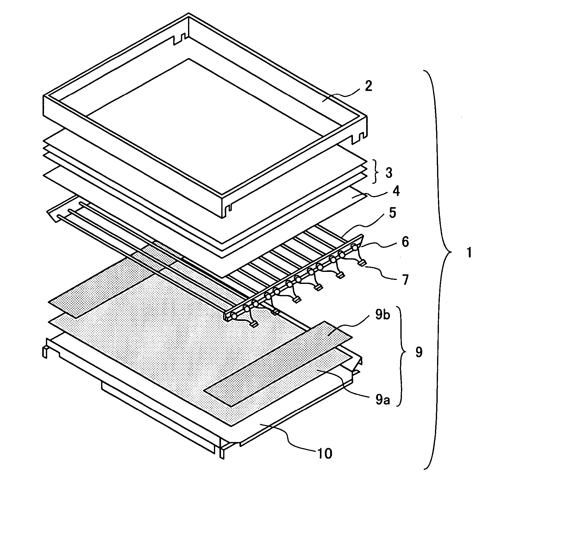
[0057] As shown in FIG. 3, a backlight unit 1 in this exemplary embodiment is constituted by a lamp 5, a lamp support 6, a lamp connector 7, a reflecting member 9, a diffuser 4, an optical sheet 3, a rear frame 10 and a center frame 2.

[0058] The lamp 5 is a plurality of tubul...

second exemplary embodiment

[0076] Next, the second exemplary embodiment of the present invention will be described. FIG. 16 is a perspective view which shows the construction of a backlight unit according to the second exemplary embodiment of the present invention in an exploded condition. FIG. 17A is a plan view which shows the positional relationship of main members of the backlight unit according to the second exemplary embodiment of the present invention. FIG. 17B is a sectional view which schematically shows the section along the line XVIIB-XVIIB in FIG. 17A as viewed from the direction of the arrow. FIG. 18 is a plan view which shows the construction of a reflecting member according to the second exemplary embodiment of the present invention.

[0077] As shown in FIG. 16, a backlight unit la in this embodiment is constituted by a lamp 5, a lamp support 6, a lamp connector 7, a reflecting member 90, a diffuser 4, an optical sheet 3, a rear frame 10 and a center frame 2. The second exemplary embodiment diff...


PUM


Abstract

Disclosed is a backlight unit which illuminates a display panel from a rear surface thereof, including at least: tubular lamps arranged in parallel to the panel; and a reflecting member which reflects light from the lamps toward the panel, wherein the reflecting member is divided into a first region opposed to an area near an electrode provided in an end portion of the lamp and a second region nearer to a middle area than the first region, the first region having a higher reflectance than the second region. In another backlight unit, a reflecting member is divided, with respect to the arrangement direction of the lamps, into an end lamp near region which is opposed to a lamp arranged in end portion and a middle region which is nearer to a middle area than the end lamp region, the end lamp region having a higher reflectance than the middle region.

Description

BACKGROUND OF THE INVENTION [0001] 1. Field of the Invention [0002] The present invention relates to a backlight unit and, more particularly, to a direct type backlight unit suitable for use in a thin-model display device of a liquid crystal and the like. [0003] 2. Description of the Related Art [0004] Liquid crystal display devices are widely used as monitors of office automation equipment and television sets and the like in terms of their characteristics, such as small size, thin design and low power consumption. The liquid crystal display device is constituted by a liquid crystal panel, in which a liquid crystal is supported by being sandwiched between opposed transparent substrates, a backlight unit which generates backlight illuminating the liquid crystal panel, and the like. As the kinds of backlight units, there have been known the direct type, the edge light type, the surface light source type and the like. The direct type is such that a light source is arranged on a rear su...

Claims


Application Information

Patent Timeline
Patent Type & Authority Applications(United States)
IPC IPC(8): F21V7/04F21Y103/37
CPCG02F1/133604G02F1/133611G02F1/133605
Inventor SUGAWARA, HIDEAKIISHIDA, HIROSHI
Owner NEC LCD TECH CORP
Why Eureka
Try Eureka