Wireless remote access base station and pico-cell system using the same
a wireless remote access and base station technology, applied in the direction of electrical equipment, content conversion, electronic repeaters, etc., can solve the problems of low sensing characteristic of rf signals and limited service coverag
- Summary
- Abstract
- Description
- Claims
- Application Information
AI Technical Summary
Benefits of technology
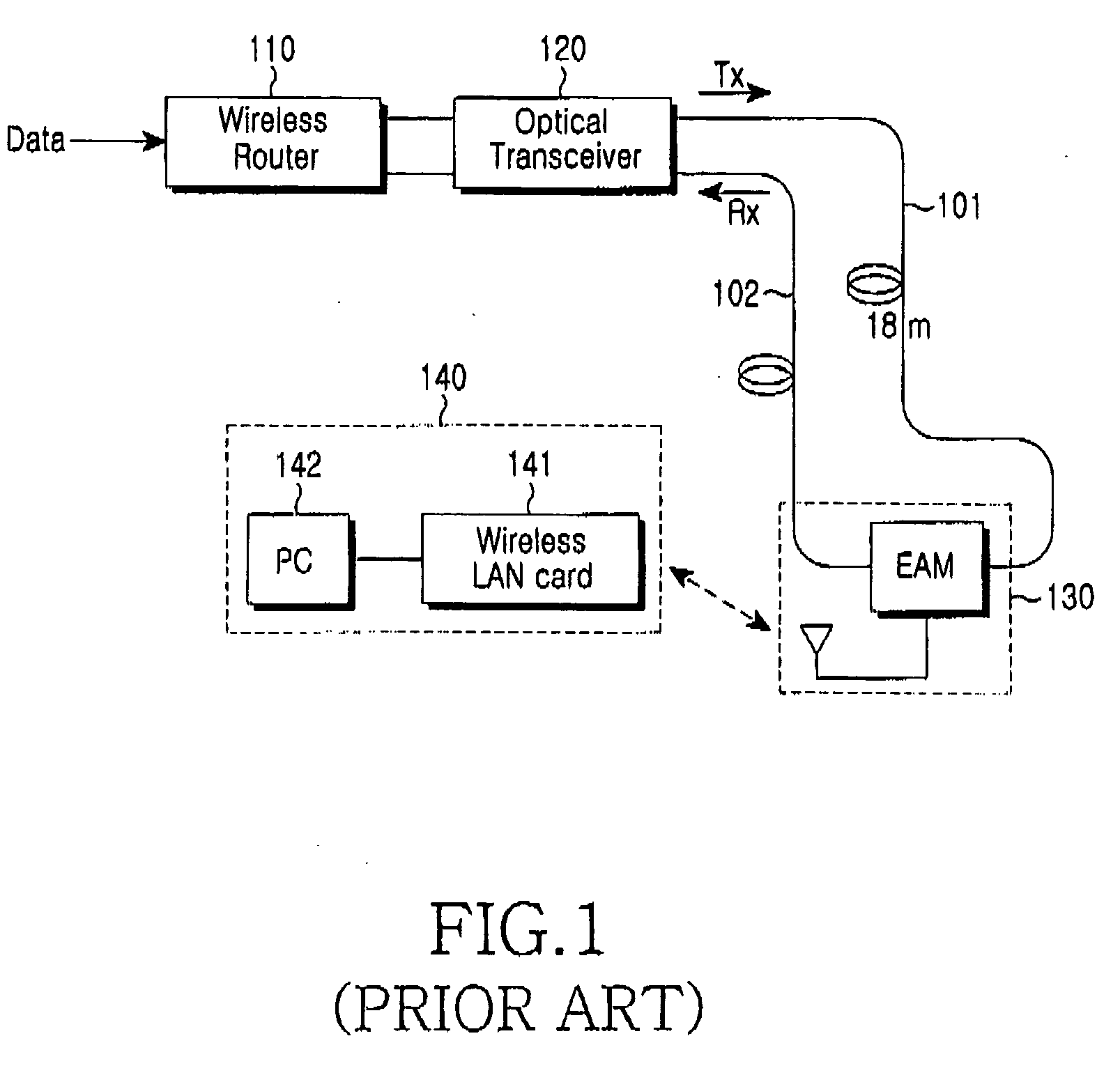
Problems solved by technology
Method used
Image
Examples
first embodiment
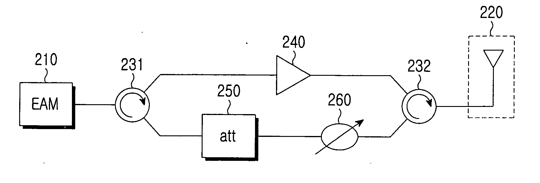
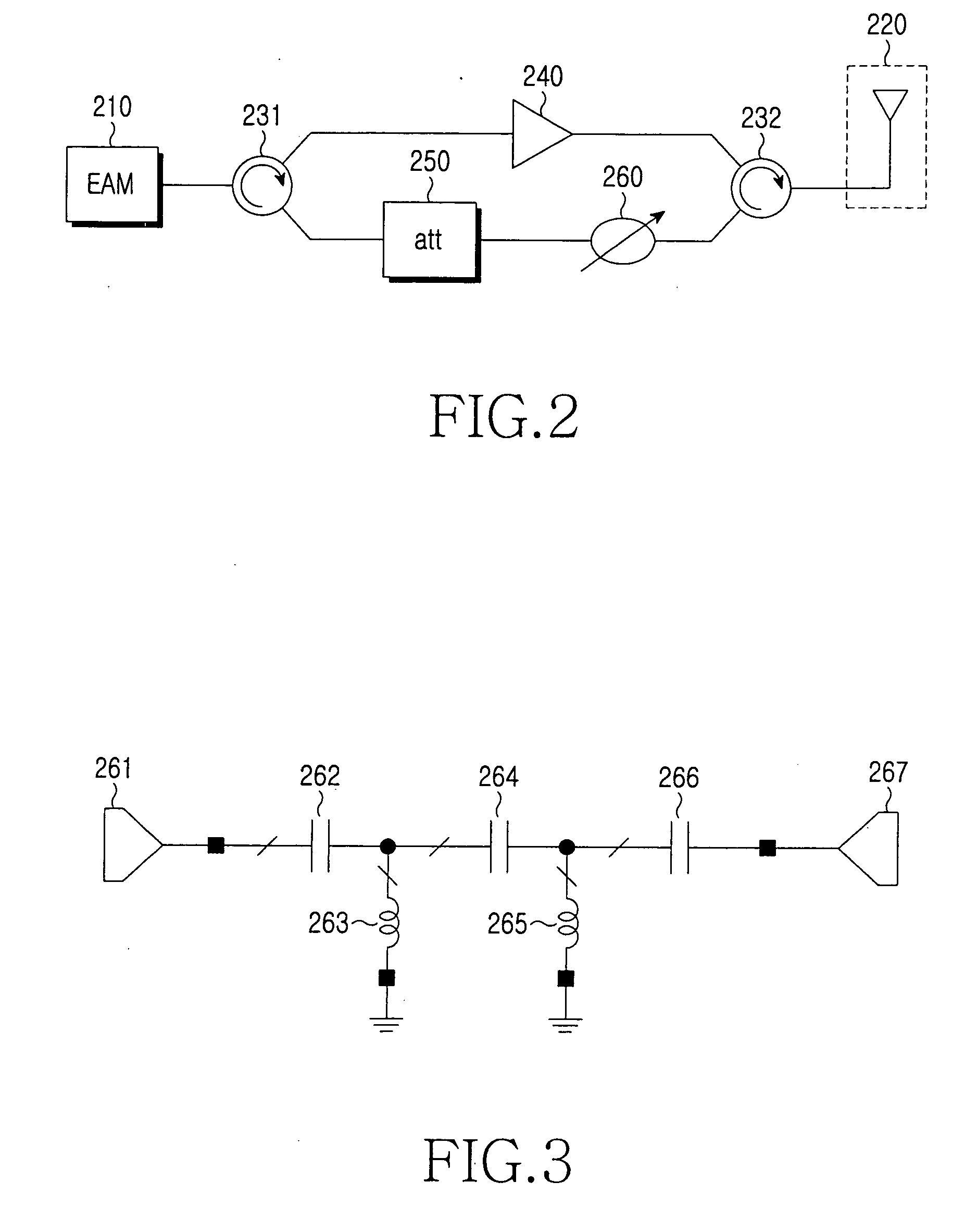
[0021]FIG. 2 is a configuration of a wireless remote access base station 200 according to the present invention. As shown, the wireless remote access base station 200 includes an electro-absorption modulator (EAM) 210 for converting a downstream optical signal to a downstream RF signal and an upstream RF signal to an upstream optical signal, an antenna 220 for transmitting the downstream RF signal wirelessly and forwarding the received upstream RF signal received wirelessly to the EAM 210, an amplifier 240, first and second circulators 231 and 232, an attenuator 250, and a filter 260.
[0022] The amplifier 240 is located between the first and second circulators 231 and 232, electrically amplifies the downstream RF signal input through the first circulator 231, and outputs the amplified downstream RF signal to the antenna 220 via the second circulator 232.
[0023] The first circulator 231 outputs the downstream RF signal to the antenna 220 and outputs the upstream RF signal received thr...
second embodiment
[0033]FIG. 6 is a configuration of a wireless remote access base station 300 according to the present invention. As shown, the wireless remote access base station 300 includes an EAM 310, an amplifier 330, a circulator 340, and an antenna 320.
[0034] The EAM 310 photoelectric converts an input downstream optical signal to a downstream RF signal and outputs the photoelectric converted downstream RF signal to the amplifier 330. The amplifier 330 amplifies the downstream RF signal and outputs the amplified downstream RF signal to the circulator 340.
[0035] The circulator 340 outputs the downstream RF signal input from the amplifier 330 to the antenna 320 and outputs an upstream RF signal input from the antenna 320 to the EAM 310.
[0036] The wireless remote access base station 300 according to the second embodiment can prevent the occurrence of oscillation in the amplifier 330 by inputting and outputting upstream and downstream RF signals through independent paths, respectively.
[0037]FI...
third embodiment
[0038]FIG. 8 is a configuration of an ROF type pico-cell system 400 according to the present invention. As shown, the pico-cell system 400 includes a wireless router 410 for generating downstream data and detecting upstream data, an optical transceiver 430 for modulating the downstream data into a downstream optical signal and outputting an upstream optical signal to the wireless router 410, a wireless communication device 420 for generating an upstream RF signal and detecting data from a received downstream RF signal, a wireless remote access base station 500, and first and second optical fibers Rx and Tx for linking the optical transceiver 430 and the wireless remote access base station 500.
[0039] The wireless communication device 420 can include a portable digital communication terminal, such as a personal computer (PC) 421 or a PDA including a WLAN card 422, and perform a duplex wireless communication by receiving a downstream RF signal and generating an upstream RF signal.
[004...
PUM
 Abstract
Description
Claims
Application Information
 - R&D
- Intellectual Property
- Life Sciences
- Materials
- Tech Scout
- Unparalleled Data Quality
- Higher Quality Content
- 60% Fewer Hallucinations
Browse by: Latest US Patents, China's latest patents, Technical Efficacy Thesaurus, Application Domain, Technology Topic, Popular Technical Reports.
© 2025 PatSnap. All rights reserved.Legal|Privacy policy|Modern Slavery Act Transparency Statement|Sitemap|About US| Contact US: help@patsnap.com


