Micro pipette sensing device

a sensing device and micro pipette technology, applied in the field of micro pipettes, can solve the problems of poor accuracy of pipette, affecting the correctness of medical or biochemical experiments or tests, and affecting the accuracy of pipette errors, so as to improve the accuracy of the overall measurement and analysis results, and improve the accuracy of the solution to be taken and transferred

a sensing device and micro pipette technology, applied in the field of micro pipettes, can solve the problems of poor accuracy of pipette, affecting the correctness of medical or biochemical experiments or tests, and affecting the accuracy of pipette errors, so as to improve the accuracy of the overall measurement and analysis results, and improve the accuracy of the solution to be taken and transferred

US20070059215A1Inactive Publication Date: 2007-03-15PACIFIC IMAGE ELECTRONICS

Image

  • Micro pipette sensing device
  • Micro pipette sensing device
  • Micro pipette sensing device

Examples


Embodiment Construction

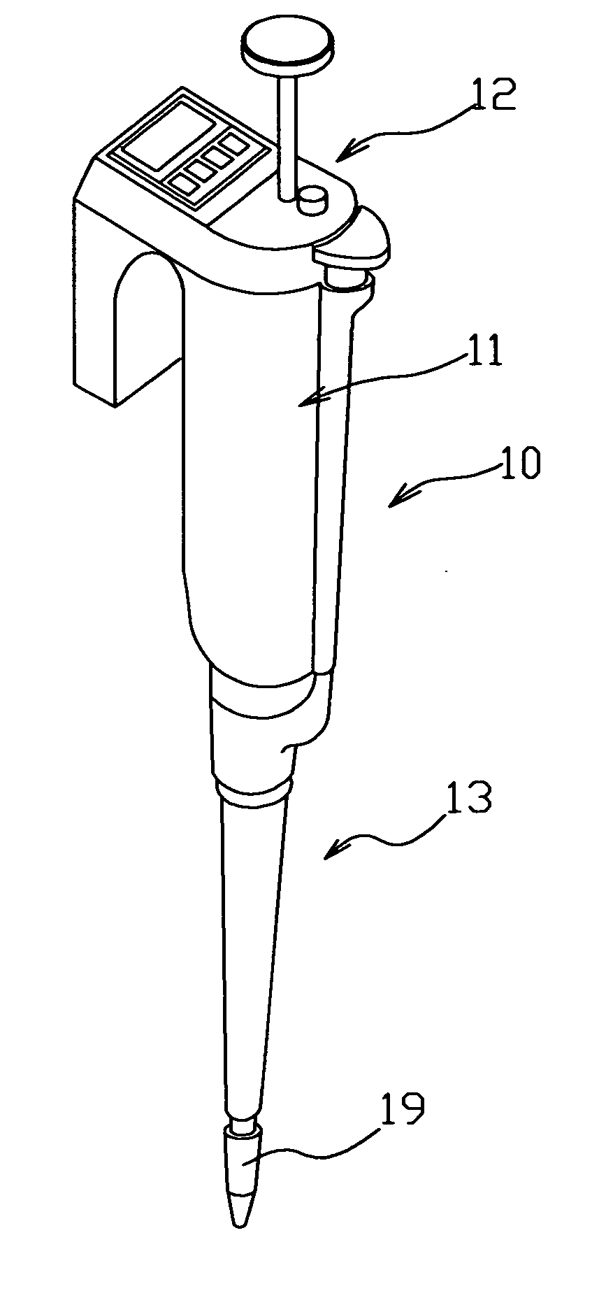
[0018] Referring to FIGS. 4 and 5, a micro pipette sensing device comprises a micro pipette 10 and a sensing device 30. The micro pipette 10 comprises a main portion 11, an operation portion 12 and a tube portion 13. The operation portion 12 may be an electronically automatic operation type or a manual operation type. The tube portion 13 may be a single-tube type or a multiple-tube type. In case of a multiple-tube type, the tube portion 13 comprises a plurality of tubes. This embodiment takes a single-tube type for example. The tube portion 13 comprises a tube wall 14. The tube wall 14 defines an operation space therein. A piston member 16 is disposed in the operation space 15. The piston member 16 connects to a piston rod 17. The piston rod 17 is driven by a step motor (not shown) to move. In this preferred embodiment, the operation space sets a top head center and a bottom head center cooperatively defining a piston stroke of the piston member 16. The tube portion 13 at a bottom t...


PUM


Abstract

A micro pipette sensing device includes a micro pipette and a sensing device. The micro pipette includes a main portion, an operation portion and at least one tube portion. The tube portion defines an operation space therein. The sensing device is located at a proper position in the operation space of the tube portion. The sensing device includes a MEMS flow sensor for sensing a gas movement in the operation space, thereby effectively improving the precision of solution to be taken and therefore improving the precision of the overall measurement and analysis results.

Description

BACKGROUND OF THE INVENTION [0001] 1. Field of the Invention [0002] The present invention relates to micro pipettes, and more particularly to a micro pipette sensing device which can sense a flow variation and feed back the flow variation information to amend it so as to obtain a more precise volume of solution to be transferred. [0003] 2. Description of Related Arts [0004] Micro pipettes are usually used in various medical and biochemical experiments, tests or analysis to take and transfer solution samples. During these medical and biochemical experiments, tests or analysis, particularly in very precise and complicated experiments such as DNA tests and analysis, the volume of the solution samples taken and transferred by the micro pipettes must be extremely precise. Imprecision of the volume of the solution sample in one single step will often cause a considerable error of the final results, or badly affect the correctness of the test and analysis results. [0005] The conventional m...

Claims


Application Information

Patent Timeline
15 Mar 2007
Publication
US20070059215A1
IPC
B01L3/02
CPC
B01L3/0227; B01L2200/143; G01F1/6888; G01F1/6845; B01L2300/0627
Inventors
HUANG, PONY