Systems and methods for an RF nulling scheme in RFID

a null scheme and null technology, applied in the field of rfid systems, can solve the problems of limiting the sensitivity of the receiver, difficult to perfectly match the impedance, and the practical limitations of minimizing signal reflection through component selection, so as to reduce the level of unwanted rf signal reflections

Active Publication Date: 2007-03-15
SMARTRAC TECH FLETCHER INC
View PDF4 Cites 74 Cited by
  • Summary
  • Abstract
  • Description
  • Claims
  • Application Information

AI Technical Summary

Benefits of technology

[0009] An RF nulling scheme can minimize the level of unwanted RF signal reflections entering the receiver without attenuating the desired signal response from an RFID tag. In one aspect of the RF nulling scheme a synthesizer sig

Problems solved by technology

Simultaneous transmission and reception can cause high levels of RF energy to enter the receiver, ultimately limiting the receiver sensitivity.
Minimizing signal reflections via component selection has practical limitations.
For example, it can be difficult to perfectly match impedance because of variability in the manufactured components used in a device or system.
These impedance mismatches can cause reflections.
Further, using separate antennas increases the system cost and requires additional space.
As discussed above, this large composite RF sig

Method used


Image

  • Systems and methods for an RF nulling scheme in RFID
  • Systems and methods for an RF nulling scheme in RFID
  • Systems and methods for an RF nulling scheme in RFID

Examples


Embodiment Construction

.”

BRIEF DESCRIPTION OF THE DRAWINGS

[0017] For a more complete understanding of the systems and methods described herein, and the advantages thereof, reference is now made to the following descriptions taken in conjunction with the accompanying drawings, in which:

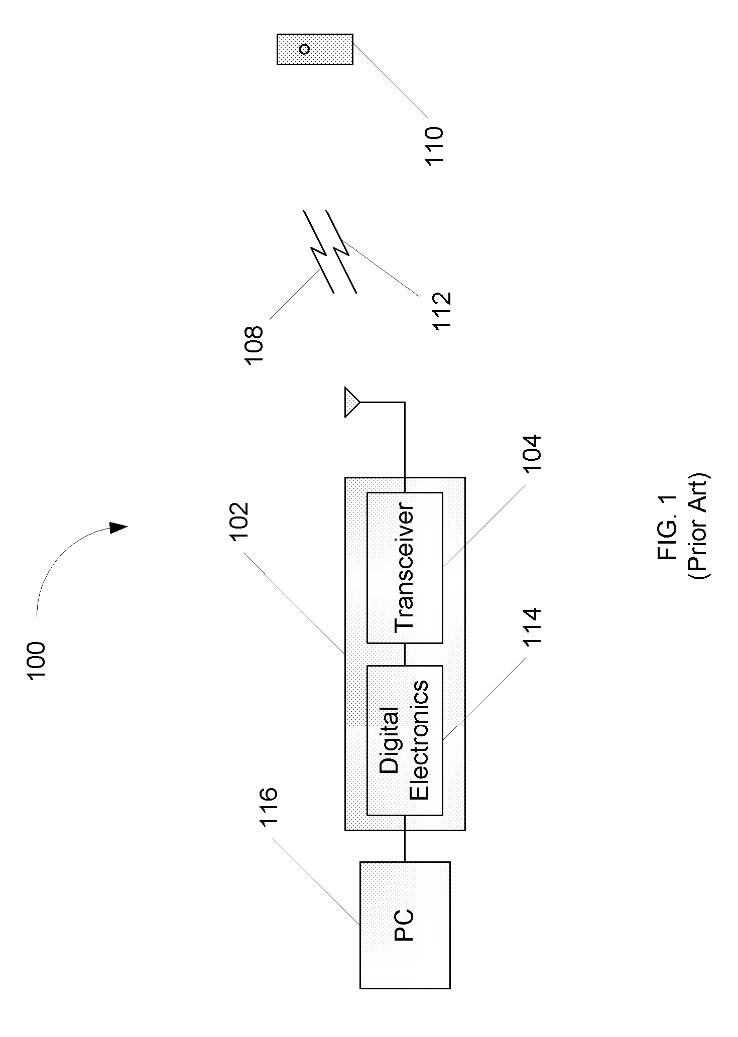
[0018]FIG. 1 is a diagram illustrating an exemplary RFID system;

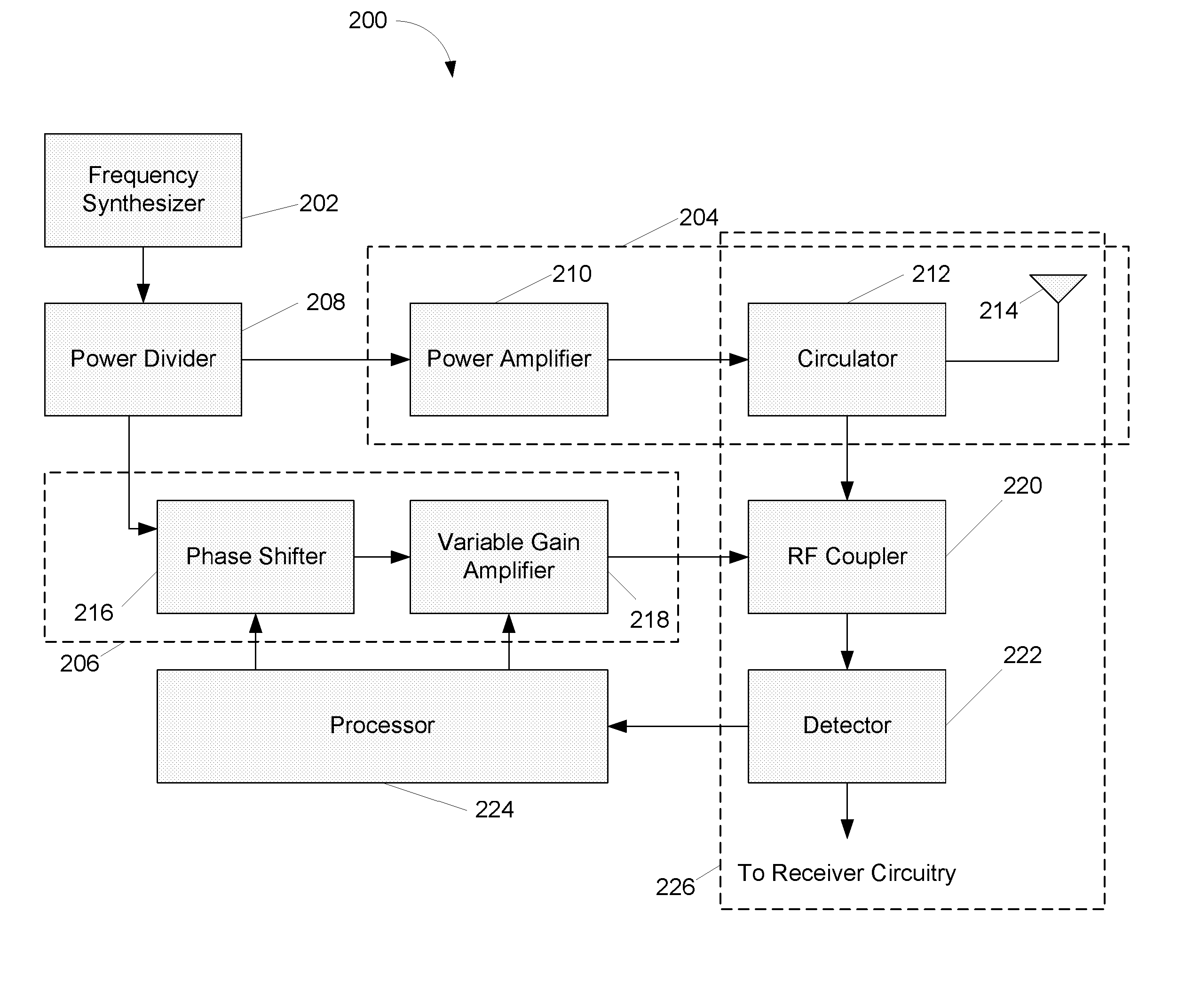
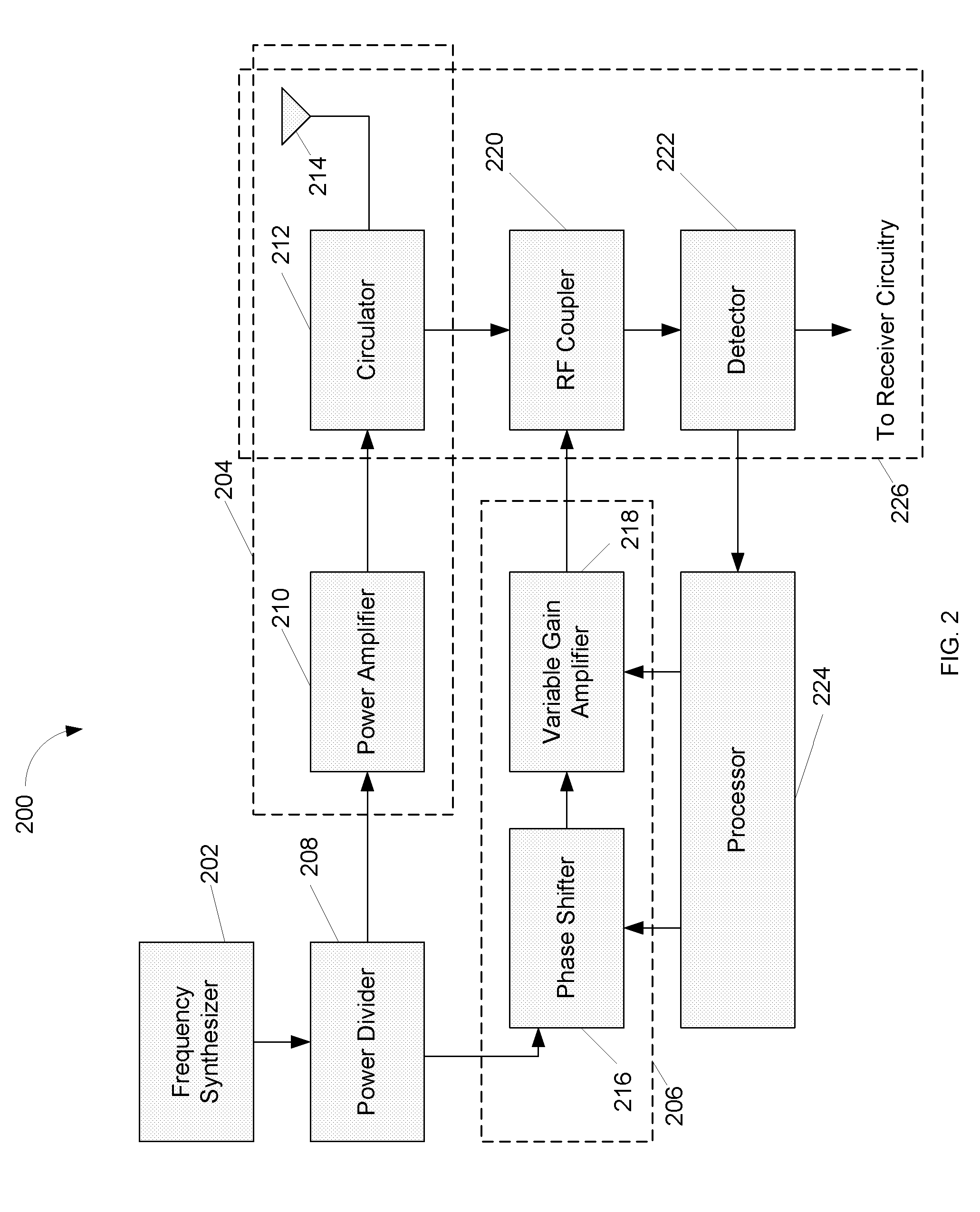
[0019]FIG. 2 is a diagram illustrating an example RFID system receiver in accordance with one embodiment;

[0020]FIG. 3 is a flowchart illustrating an example method of RF nulling that can use the system of FIG. 2 in accordance with one embodiment; and

[0021]FIG. 4 is a flowchart illustrating another example method of RF nulling that can use the system of FIG. 2 in accordance with one embodiment.

DETAILED DESCRIPTION

[0022]FIG. 2 is a diagram illustrating an example RFID System Receiver 200 in accordance with one embodiment. In this embodiment, an RF nulling scheme can be used to minimize the level of reflected RF signals entering a receiver without attenuating...


PUM


Abstract

Systems and methods for an RF nulling scheme are provided. An RF nulling scheme can minimize the level of unwanted RF signal reflections entering the receiver without attenuating the desired signal response from an RFID tag. In one aspect of the RF nulling scheme a synthesizer signal can be split between a main path and a nulling path. In the nulling path the signal from the splitter can be routed through an electronically variable phase shifter and variable gain amplifier to create a nulling signal. The nulling signal can cancel the unwanted reflected signal. The phase or amplitude of the nulling signal can then be adjusted to improve cancellation as necessary.

Description

RELATED APPLICATION INFORMATION [0001] This application is based upon and claims the benefit of priority from U.S. Provisional Patent Application Ser. No. 60 / 717,013, filed Sep. 14, 2005, the entire contents of which are incorporated herein by reference.BACKGROUND [0002] 1. Field of the Invention [0003] The present embodiments described herein relates generally to RFID systems, and more particularly to systems and methods for RF nulling within an RFID system. [0004] 2. Background of the Invention [0005]FIG. 1 is a diagram illustrating an exemplary RFID system 100. In system 100, RFID interrogator 102 communicates with one or more RFID tags 110. Data can be exchanged between interrogator 102 and RFID tag 110 via radio transmit signal 108 and radio receive signal 112. RFID interrogator 102 comprises RF transceiver 104, which contains transmitter and receiver electronics, and antenna 106, which are configured to generate and receive radio transmit signal 108 and radio receive signal 11...

Claims


Application Information

Patent Timeline
IPC IPC(8): H01Q11/12
CPCG06K7/0008H01Q1/22H04B1/525H01Q3/2611H01Q1/2225
Inventor MIKUTEIT, ERIC
Owner SMARTRAC TECH FLETCHER INC
Why Eureka
Try Eureka