Machining of Ceramic Materials

a technology of ceramic materials and machining, which is applied in the field of lithium silicate materials, can solve the problems of difficult to combine the properties of low strength in the material stage, difficult to achieve the effect of reducing machining time, reducing machining time, and maintaining strength

Active Publication Date: 2010-03-11
IVOCLAR VIVADENT AG
View PDF16 Cites 18 Cited by
  • Summary
  • Abstract
  • Description
  • Claims
  • Application Information

AI Technical Summary

Benefits of technology

[0016]Additional aspects of the embodiments of the invention are directed to a method of reducing the time for machining a dental ceramic blank, wherein the fracture toughness (Klc) and the flexural strength (σf) of the dental ceramic material are known, comprising calculating an estimate of the maximal surface critical flaw size and an estimate of the maximal volume critical flaw size of the dental ceramic using the following formula:c=(Klc / σf)2
[0024]Milling with diamond tools (grinding) is quite different from milling with fluted tools (cutting). Diamond tools either comprise a coating with embedded diamonds or a matrix with embedded diamonds dispersed through the whole thickness of a tool. In both cases, embedded diamonds are characterized by a grain size distribution, range of grain sizes, grit size, and / or average grain size. Very often embedded diamonds are referred to as diamond grit. During machining, high contact stresses are generated on the interface between a work-piece and a tool. With all things being equal, it is beneficial to minimize the level of those stresses while maximizing material removal rate. The local stress condition on the milled surface in immediate contact with the diamond tool is very complex and is characterized by a stress tensor with all nine components changing in time. When a chip of material is cleaved away by the advancing diamond, the strain energy is released and when the next diamond hits the milled surface the stress begins building up again. It should be noted that many of these stress tensor components are parasitic and do not contribute to the effective machining process by cleaving off chips of material, but rather to tool wear by diamond pull-out. The volume of material to be removed is provided by subtracting the net shape of the dental article to be milled from the blank shape and separating it into regions requiring different material removal rates, accuracy and surface roughness. The regions are allocated to one or more of a rough, intermediate and fine machining step along with a specific tool path, which is calculated for each of the allocated machining steps. The purpose of the rough machining step is to approximate to the near net shape in the minimum amount of time (accuracy and surface roughness are not important). Intermediate machining is utilized to get closer to the net shape and is sufficient where surface roughness and accuracy are not so important (e.g., such as with the internal lateral surfaces of the coping or crown, which will be ultimately sealed by cement or adhesive). Fine machining is required for high accuracy and for a fine surface finish, such as at the margin of the restoration underside, which will carry most of the global loading. It was found that there is a synergy between simultaneous 5-axis milling and the use of conical diamond tools having round tips, allowing an optimal “angle of attack” to avoid introduction of dangerous, strength limiting flaws and allow more aggressive grinding. As a result, feed rates and material removal rates are maximized without noticeable compromise in strength. The rough, intermediate and fine machining steps are further dependent on the difference in volume of the dental ceramic blank and the machined net shape of the dental article and further dependent on the final roughness and accuracy of the machined net shape.
[0027]In additional aspects, the machining parameters may include tool specifications, revolutions per minute, linear speeds, feed rate (mm / min), feed per rotation (microns), depth of cut (microns) and material removal rate. Possible ranges for revolutions per minute (RPM) are from 30,000 to 100,000 revolutions per minute and preferably from 30,000 to 60,000 revolutions per minute. Possible ranges of the feed rate include approximately 500 mm / min to approximately 5000 mm / min. The depth of cut may range from approximately 10 microns to approximately 150 microns, preferably from about 10 microns to about 130 microns. It is preferable that the depth of cut is smaller than the grain size of the embedded diamonds and that the feed per rotation is smaller than the depth of cut. It is further preferable that the depth of cut is smaller than the estimated maximal value of the surface critical flaw size for fine machining and larger than the estimated maximal value of the surface critical flaw size for rough machining. The series of tools may include conical diamond tools having round tips and coated with diamond grains having different sizes. The conical form gives the grinding device much more rigidity against vibrations. The machining strategy in combination with the series of diamond tools reduce machining time while maintaining strength, accuracy and marginal integrity. For certain types of machinable ceramic materials carbide tools may also be used.

Problems solved by technology

The difficulty of combining the properties of low strength in the stage of the material to be processed and a high strength of the final restoration is reflected by the known materials for a CAD / CAM processing which are in particular with respect to an easy machinability unsatisfactory.
However, it has been shown that the machining of these materials results in a very high wear of the tools and very long processing times. These disadvantages are caused by the high strength and toughness primarily imparted to the materials by the lithium disilicate crystalline phase.
Moreover, it has been shown that the machined restorations show only a poor edge strength.
However, these ceramic materials suffer from a drastical shrinkage of up to 50% by volume (or up to 30% as linear shrinkage) during the final sintering step.
This leads to difficulties in preparing the restorations with exactly the dimensions as desired.
The substantial shrinkage represents a particular problem if complicated restorations are manufactured, such as a multi-span bridge.

Method used


Image

  • Machining of Ceramic Materials
  • Machining of Ceramic Materials
  • Machining of Ceramic Materials

Examples


example 1

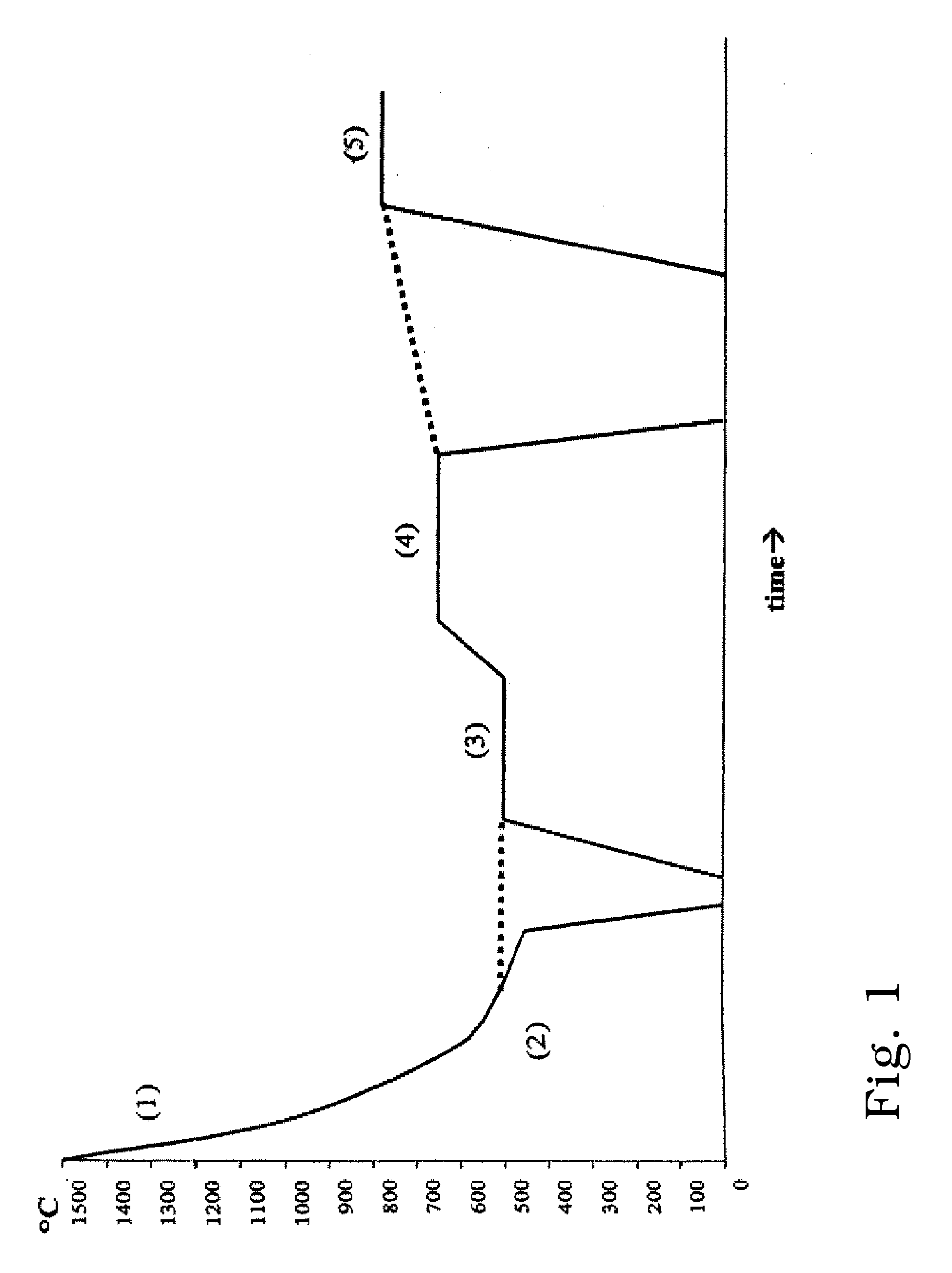
[0172]The glass was molten at a temperature of 1500° C. for 3 hours and was then poured into steel moulds which were preheated to 300° C. After one minute the glass bars were transferred into a cooling furnace and were tempered at 500° C. for 10 minutes and then cooled to room temperature.

[0173]The glass was homogeneous and transparent.

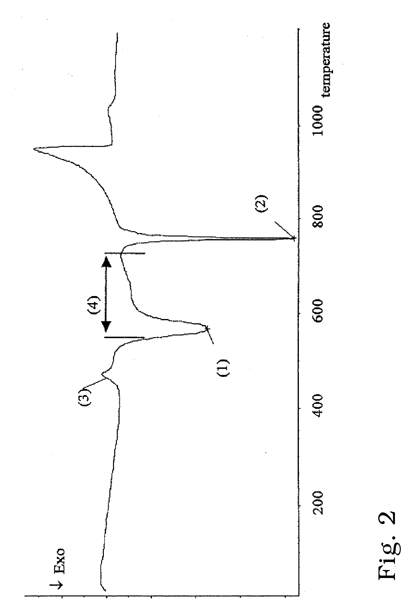
[0174]Following the glass bar was subjected to a first crystallization at 650° C. for a period of 20 minutes.

[0175]From the such ceramized bar, discs were sawn out of a round bar, and biaxial strength was measured. The phase content was analyzed via XRD (X-ray diffraction). Lithium metasilicate was the only phase that was detected. Biaxial strength was 119+ / −25 MPa.

[0176]Also the milling time of test bodys was measured. The milling time of the test body was one minute below that of ProCAD®, which was used as reference.

[0177]The edge strength was good.

[0178]Additional 10 discs were subjected to a second crystallization at 850° C. for a period of 10 min...

example 6

[0183]Glass bars were produced according to example 1. The glass again was homogeneous and transparent.

[0184]The first crystallization was performed at 650° C. for a period of 20 minutes.

[0185]Lithium metasilicate was determined to be the main phase with traces of lithium disilicate also being present. Biaxial strength was 135+ / −24 MPa.

[0186]Again the milling time of a test body was measured. The milling time of the test body was one minute below that of ProCAD®, which again was used as reference.

[0187]The edge strength was very good.

[0188]After a second crystallization which was performed according to example 1 the biaxial strength was 472+ / −85 MPa which correlates to a Strength Increase Factor of 3.5.

[0189]Fracture toughness (IF) was 2.3 MPam0.5.

[0190]Translucence was extraordinary.

example 9

[0191]Glass bars were produced according to example 1. The glass again was homogeneous and transparent.

[0192]The first crystallization was performed at 650° C. for a period of 20 minutes.

[0193]Lithium metasilicate was determined to be the only phase. Biaxial strength was 112+ / −13 MPa.

[0194]Again the milling time of a test body was measured. The milling time of the test body was one minute below that of ProCAD®, which again was used as reference.

[0195]The edge strength was good.

[0196]After a second crystallization which was performed according to example 1 the biaxial strength was 356+ / −96 MPa which correlates to a Strength Increase Factor of 3.16.

[0197]Fracture toughness (I F) was 1.9 MPam0.5.

[0198]Translucence was acceptable.


PUM

PropertyMeasurementUnit
fracture toughnessaaaaaaaaaa
grain sizeaaaaaaaaaa

Abstract

Milling strategies for machining dental ceramic materials are provided that reduce milling time while maintaining strength, accuracy and marginal integrity.

Description

CROSS-REFERENCE TO RELATED APPLICATIONS[0001]This application is a continuation in part of U.S. patent application Ser. No. 11 / 935,203, filed Nov. 5, 2007, which is of division of U.S. patent application Ser. No. 10 / 913,095, filed Aug. 6, 2004, which claims priority to German Patent Application Serial No. 103 36 913.9, filed Aug. 7, 2003, all of which are herein incorporated by reference in their entirety.FIELD OF THE INVENTION[0002]The invention relates to lithium silicate materials which can be easily shaped by machining and subsequently converted into shaped products with high strength.BACKGROUND OF THE INVENTION[0003]There is an increasing demand for materials which can be processed into dental restorative products, such as crowns, inlays and bridges, by means of computer controlled milling machines. Such CAD / CAM methods are very attractive as they allow to provide the patient quickly with the desired restoration. A so-called chair-side treatment is thus possible for the dentist...

Claims


Application Information

Patent Timeline
Patent Type & Authority Applications(United States)
IPC IPC(8): A61C5/10A61C5/77A61K6/838
CPCA61C3/02A61C5/10A61C13/0003A61C13/0004Y10T29/49567A61C13/083C03C4/0021C03C10/00C03C10/0027A61C13/0022A61C5/77Y10T83/05
Inventor HEINZ, MARKUSRINNER, KLAUSGORFER, GEORGASTER, MARIUSSCHWEIGER, MARCELBRODKIN, DMITRI
Owner IVOCLAR VIVADENT AG
Why Eureka
Try Eureka