Receiver, frequency deviation measuring unit and positioning and ranging system

a technology of measuring unit and receiver, which is applied in the direction of multi-frequency-changing modulation transference, instruments, transmission monitoring, etc., can solve the problems of low accuracy in ranging, inability to identify the position of the transmitter, and inability to cause errors in ranging, so as to reduce power consumption, size and cost, accurate time difference

Inactive Publication Date: 2007-03-15
HITACHI LTD
View PDF14 Cites 44 Cited by
  • Summary
  • Abstract
  • Description
  • Claims
  • Application Information

AI Technical Summary

Benefits of technology

[0015] According to the present invention, an accurate time difference can be measured using a low-speed clock, control signal, and counter, so tha

Problems solved by technology

One of challenges in positioning/ranging systems is improvements in positioning accuracy.
In other words, errors and low accuracy in the ranging can be caused by a frequency deviation of the oscillator in one of the transmitter and receiver from the oscillator in the other one.
The system described in JP-A-2004-254076 can detect a change in the distance between a transmitter and a receiver, but cannot identify the position of the transmitter.
In other words, errors in the ranging can be caused by a frequency d

Method used


Image

  • Receiver, frequency deviation measuring unit and positioning and ranging system
  • Receiver, frequency deviation measuring unit and positioning and ranging system
  • Receiver, frequency deviation measuring unit and positioning and ranging system

Examples


first embodiment

[First Embodiment]

[0041] A receiver according to a first embodiment of the present invention, and a positioning / ranging system using the same will be described with reference to FIGS. 1 to 12. First, the configuration and operation of the system in the first embodiment will be outlined with reference to FIGS. 1 to 3.

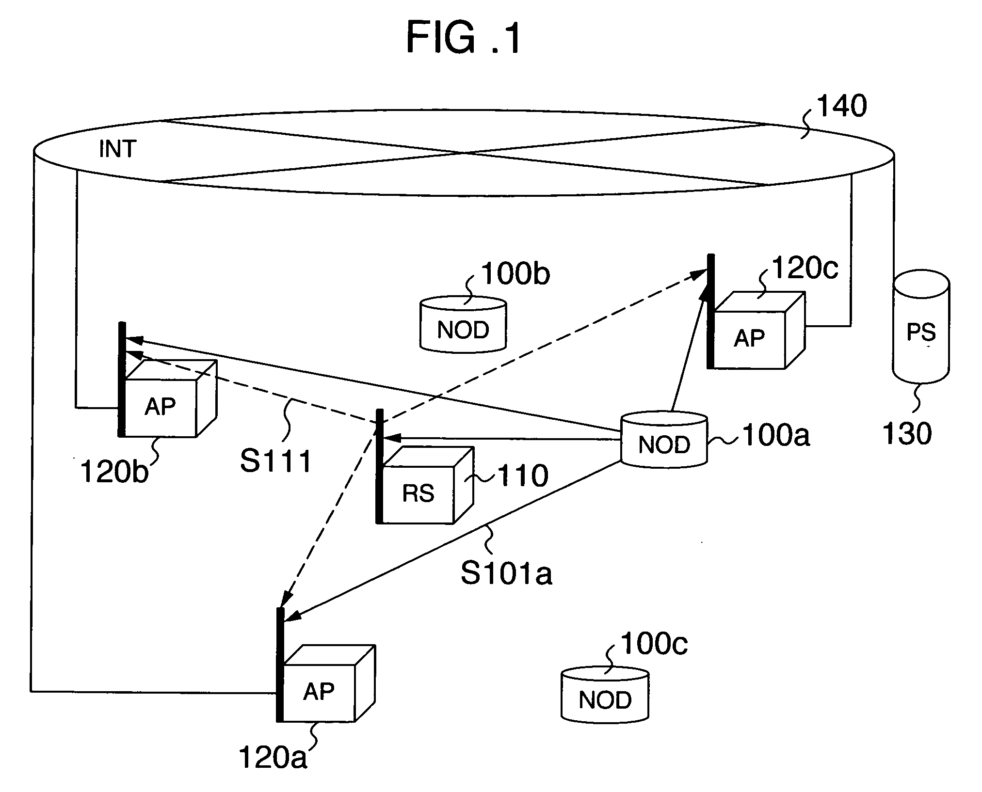
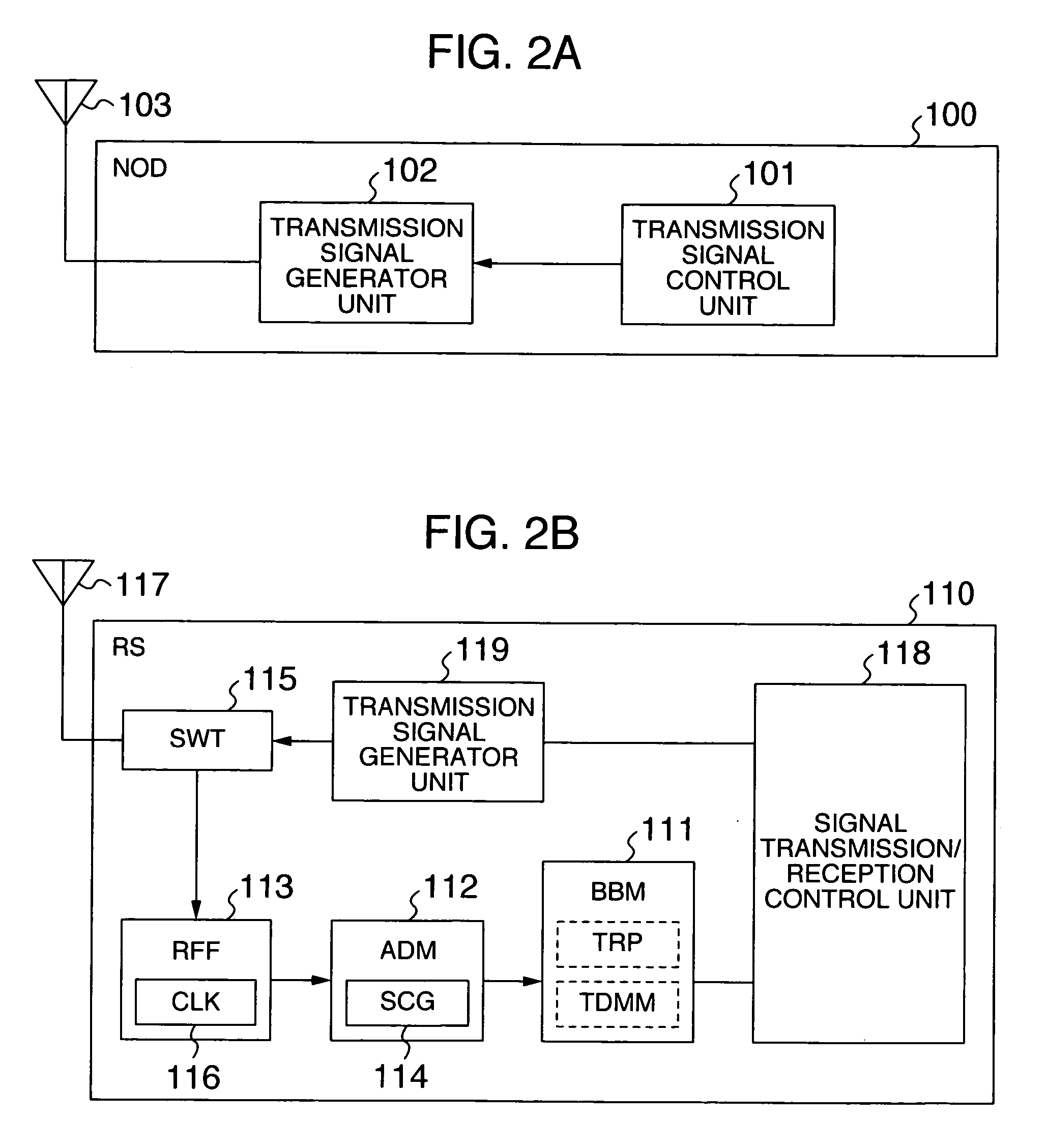
[0042]FIG. 1 illustrates the configuration of the positioning / ranging system according to the first embodiment of the present invention. The positioning / ranging system comprises a plurality of nodes (NOD) 100 (100a, 100b, . . . ) (which are intended for positioning) each for transmitting a positioning signal; a reference station (RS) 110 for transmitting a reference signal; a plurality of access points (AP) 120 (120a, 120b, 120c) each for receiving the positioning signal and reference signal; a positioning server (PS) 130; and a network (INT) 140 for interconnecting the respective access points 120 and positioning server 130. It should be noted that the suffixes a, b, c...

second embodiment

[Second Embodiment]

[0123] Next, a frequency deviation measuring unit for measuring and reducing a clock error between access points according to a second embodiment of the present invention will be described with reference to FIGS. 13 to 15.

[0124] In the first embodiment of the present invention described above, the reception time difference Tmeas measured by the access point 120 includes an error due to the accuracy of the clock frequency.

[0125] The positioning server 130 calculates the position of the node 100 in accordance with Equation (2) using the reception time differences Tmeas measured by a plurality of access points 120. When a clock error is taken into consideration, the second term on the right side of Equation (2) is: Tmeas,a-Tmeas,b=⁢Treal,a·(1+δa)-Treal,b·(1+δb)=⁢Treal,a-Treal,b+(Treal,a·δa-Treal,b·δb)(4)

resulting in an error (Treal,a·δa+Treal,b·δb), where Treal,a, Treal,b represent real times which should be measured by the access points 120a, 120b, respectively,...

third embodiment

[Third Embodiment]

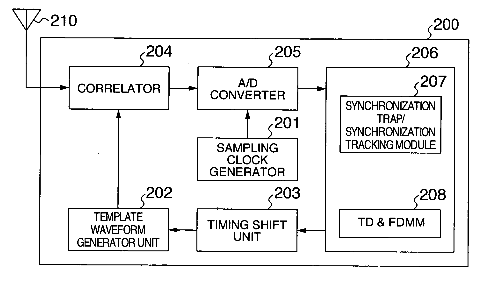
[0139] Next, a third embodiment of the present invention will be described with reference to FIGS. 16 to 19. A receiver of this embodiment comprises the function of the frequency deviation measuring unit in the second embodiment added to the receiver of the first embodiment. FIG. 16 is a diagram illustrating the configuration of a baseband module 440 which comprises a time difference measuring function and a deviation measuring function. FIG. 17 is a diagram illustrating an exemplary configuration of a time difference / frequency deviation measurement module (TD&FDMM) 1310.

[0140] In FIGS. 16 and 17, the time difference / frequency deviation measurement module (TD&FDMM) 1310 is applied with a sampling clock S435d, sampling timing control signals S441, S442, an SFD detection signal S551, and a data end signal S552, and outputs a measured time difference S444a and deviation S444b.

[0141] The time difference / frequency deviation measurement module 1310 comprises counters 6...


PUM


Abstract

In a system for measuring a time difference of arrival of signals for positioning, an accurate time difference is measured by a receiver which is reduced in power consumption, size, and cost. The system comprises a node (under measurement) for transmitting a positioning signal, a reference station for transmitting a reference signal, and a plurality of access points for receiving the positioning signal and reference signal, and a server connected to the plurality of access points through a network. Each of the plurality of access points measures a time difference between the reception of the positioning signal and the reception of the reference signal, and a frequency deviation from the reference station, using a clock signal and a signal for shifting the clock signal, and the server calculates the position of the node based on the measured time difference and frequency deviation.

Description

BACKGROUND OF THE INVENTION [0001] The present invention relates to a receiver and a frequency deviation measuring unit which are suitable for measuring the position of a terminal node having radio communication capabilities, and a positioning and ranging system which employs the receiver and frequency deviation measuring unit. [0002] Public attention has been attracted by a wireless sensor network (hereinafter simply called the “sensor net”) which includes devices having sensing capabilities installed everywhere around a region to form a network over the air, thereby efficiently capturing information in the real world into an information network such as the Internet. In concept, the sensor net is autonomously built by an infinite number of nodes (terminals), each of which comprises a sensor, a microcomputer, a radio communication device, and a power supply and measures situations relating to persons, objects, environment and the like by the sensor. The sensor net is now under inves...

Claims


Application Information

Patent Timeline
IPC IPC(8): H03D7/16G01S5/06H04W64/00
CPCH04J3/0682G01S5/06H04B17/00
Inventor NAKAGAWA, TATSUOMIYAZAKI, MASAYUKIMIZUGAKI, KENICHIFUJIWARA, RYOSUKE
Owner HITACHI LTD
Why Eureka
Try Eureka