Ophthalmic injector

a technology of ophthalmic injection and injector, which is applied in the field of posterior segment ophthalmic injection, can solve the problems of increased manufacturing cost and potential reliability problems, catheterized drug delivery is not suitable for ophthalmic applications, and the posterior segment of the eye continues to threaten vision

Inactive Publication Date: 2007-03-15
ALCON RES LTD
View PDF90 Cites 42 Cited by
  • Summary
  • Abstract
  • Description
  • Claims
  • Application Information

AI Technical Summary

Benefits of technology

[0006] In one aspect, the present invention is an ophthalmic injector including a nose cone, a dosage form, a needle, a plunger assembly, and a heater assembly. The nose cone has a heating chamber. The dosage form is in a solid state and is disposed in the heating chamber. The needle is fluidly coupled to the heating chamber, and the plunger assembly has a rod at lea...

Problems solved by technology

However, such a coil design may result in increased manufacturing cost and potential reliability issues.
However, catheterized drug delive...

Method used


Image

  • Ophthalmic injector
  • Ophthalmic injector
  • Ophthalmic injector

Examples


Embodiment Construction

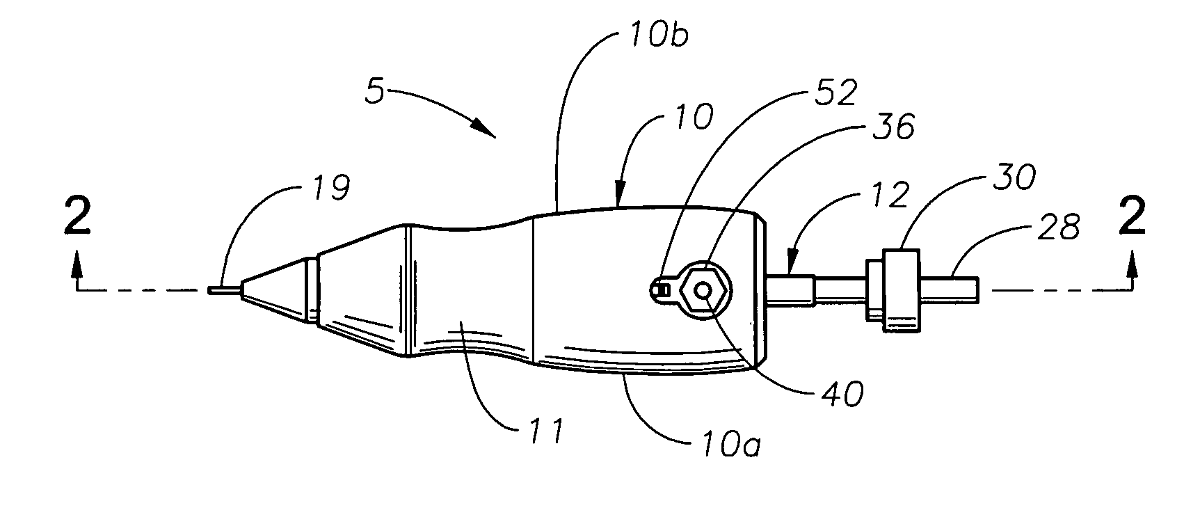
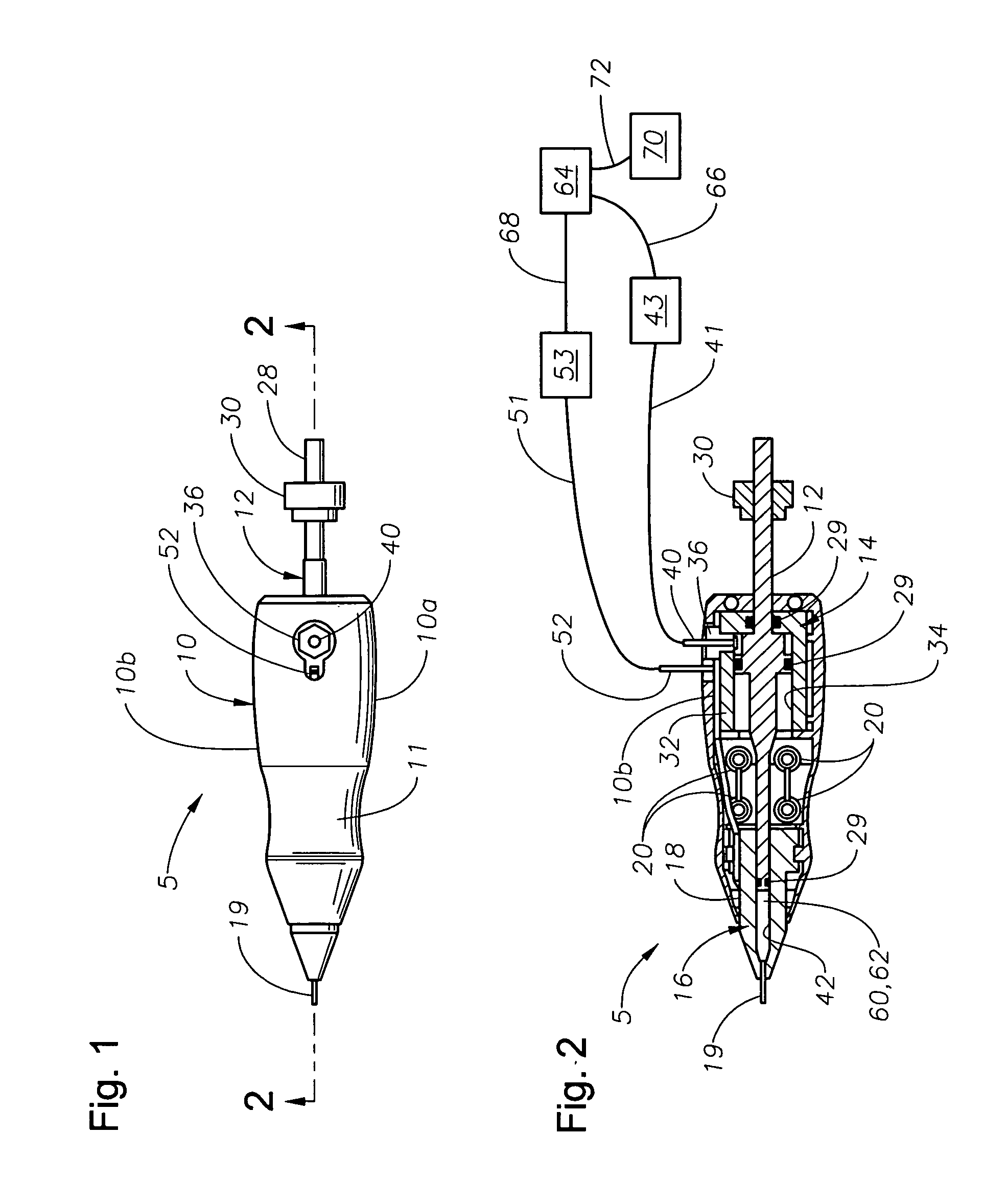
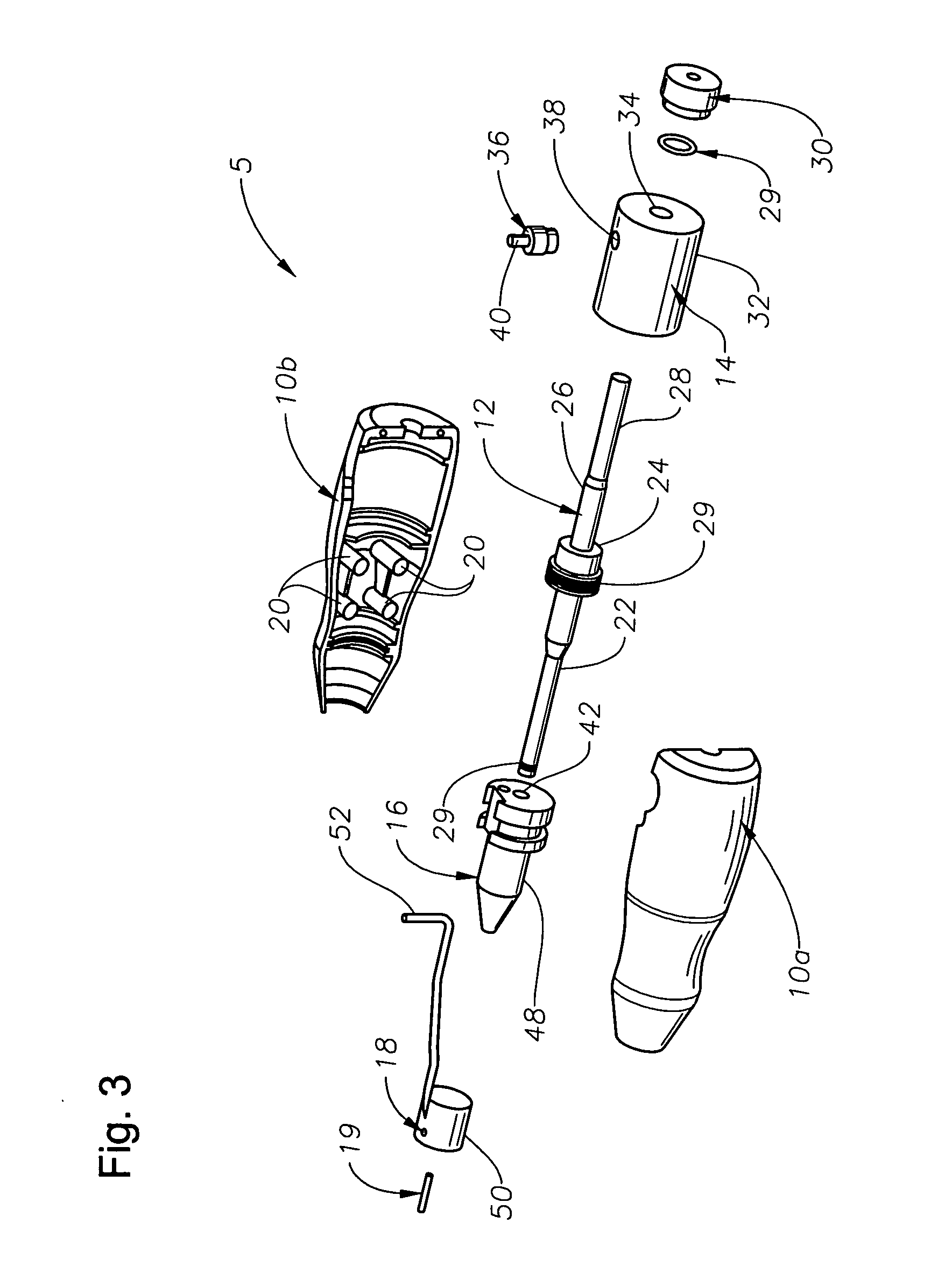
[0012] The preferred embodiments of the present invention and their advantages are best understood by referring to FIGS. 1-3 of the drawings, like numerals being used for like and corresponding parts of the various drawings.

[0013] Ophthalmic injector 5 generally includes a housing 10, a plunger assembly 12, an actuation assembly 14, a nose cone 16, a heater assembly 18, a needle 19, and a dosage form 60. Housing 10 includes a left housing 10a and a right housing 10b that are removably and frictionally coupled via pin mounts 20 and pins (not shown). Housing 10 preferably includes a region 11 for grasping ophthalmic injector 5. Plunger assembly 12 preferably includes a distal rod 22, a base 24, and a proximal rod 26. Rod 26 has a threaded end 28 for rotationally coupling with an adjustment nut 30. Plunger assembly 12 also includes o-rings 29 for fluidly sealing to various surfaces of ophthalmic injector 5. Actuation assembly 14 is preferably a cylinder 32 having a bore 34 for receivi...


PUM


Abstract

An ophthalmic injector having a nose cone with a heating chamber, a heater assembly, and a needle that provide improved drug delivery.

Description

[0001] This application claims the priority of U.S. Provisional Application No. 60 / 710,046 filed Aug. 22, 2005.FIELD OF THE INVENTION [0002] The present invention generally pertains to ophthalmic drug delivery and more particularly to posterior segment ophthalmic drug delivery. DESCRIPTION OF THE RELATED ART [0003] Current intravitreal drug delivery devices deliver drugs to the vitreous through the pars plana region of the eye, which is devoid of retinal tissue, to avoid complications such as retinal detachment. Examples include the VITRASERT® implant and the RETISERT® implant available from Bausch & Lomb, both of which require a relatively large pars plana incision (e.g. 1-5 mm) for implantation. The OCUSERT device, which has been used to deliver pilocarpine for the treatment of glaucoma, employs a pars plana injection of biodegradable or bioerodible pellets through a 22 gauge needle, which is not “self-sealing” procedure. [0004] U.S. Pat. No. 4,030,499 to Bucalo discloses a syring...

Claims


Application Information

Patent Timeline
IPC IPC(8): A61F7/12
CPCA61F7/12A61F9/0017A61F9/007A61M2210/0612A61M5/445A61M2205/3653A61F9/00781
Inventor MARSH, DAVID A.RODSTROM, THERON R.WEINER, ALAN L.
Owner ALCON RES LTD
Why Eureka
Try Eureka