
Surgical instrument

a surgical instrument and a technology for surgical instruments, applied in the field of surgical instruments, can solve the problems of multiple sterile instruments, inability to obtain proper instruments, constant use of plastibell methods, etc., and achieve the effect of simple use and economic manufactur

Inactive Publication Date: 2007-03-15
DAVE AMAR L +1
View PDF13 Cites 15 Cited by
  • Summary
  • Abstract
  • Description
  • Claims
  • Application Information

AI Technical Summary

Benefits of technology

[0011] Another object of the present invention is to provide a surgical instrument for performing circumcisions which does not require use of sterile forceps and clamps to hold foreskin during the circumcision procedure.
[0012] Yet another object of the present invention is to provide a surgical instrument for performing circumcisions which does not require use of sterile scissors or other cutting tools.
[0013] A further object of the present invention is to provide a surgical instrument for performing circumcisions which eliminates slippage and retraction of the foreskin.
[0015] An additional object of the present invention is to provide a surgical instrument for performing circumcisions which is economical to manufacture.
[0016] Another object of the present invention is to provide a surgical instrument for performing circumcisions which is simple to use.

Problems solved by technology

Several problems are constantly encountered in using the existing Plastibell method.
The first problem is encountered in that the foreskin may slip and retract during the procedure thus often leading to another circumcision or even to adhesion of the foreskin to the glans.
The second problems is encountered in that the sterile forceps are required to hold the outer edge of the foreskin and sterile scissors or other cutting tools are required to cut off the foreskin portion.
The need for multiple sterile instruments poses difficulties in certain geographical areas where sterilization procedures may be of less than desirable quality and proper instruments may not be available.

Method used


Image

  • Surgical instrument
  • Surgical instrument

Examples


Embodiment Construction

[0022] Prior to proceeding to the more detailed description of the present invention, it should be noted that, for the sake of clarity and understanding, identical components which have identical functions have been identified with identical reference numerals throughout the several views illustrated in the drawing figures.

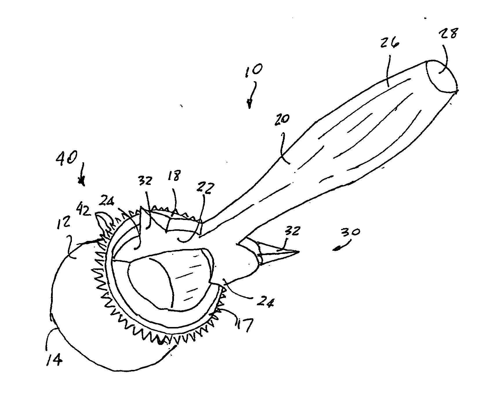
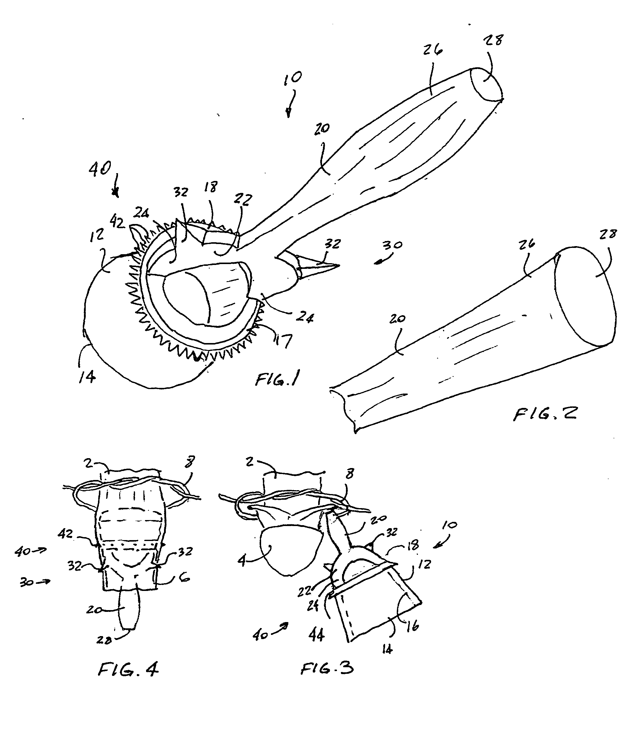
[0023] Reference is now made, to FIGS. 1-4, wherein there is shown a surgical device, generally designated as 10, for performing a circumcision. The construction of the surgical device 10 is similar to the surgical device taught in U.S. Pat. No. 3,056,407 issued Oct. 2, 1962 to Kariher et al and the disclosure of U.S. Pat. No. 3,056,407 is incorporated into this document by reference thereto.

[0024] The surgical device 10 includes a hollow body 12 which is open at both ends thereof. The body 12 includes an interior surface 16 thereof being conically shaped and tapered to define an enlarged opening at a posterior end 14 of the body 12. As it is well known, the dev...


PUM


Abstract

A surgical device for performing a circumcision includes a hollow body open at both ends thereof. A Y-shaped handle is positioned adjacent an anterior end of the body and has each leg secured to one of two diametrically opposed points on the anterior end. Each leg has a portion thereof disposed adjacent a juncture with the anterior end of the body being weaker than any other portion of the body, whereby a reciprocation of the handle causes the handle to fracture at each juncture and become detached from the body. A pair of pointed barbs are rigidly attached to a predetermined portion of the handle for positively retaining a distal portion of the foreskin. A plurality of pointed barbed serrations are formed adjacent the anterior end of the body for separating the distal portion of the foreskin. The handle has a rounded distal end for separating the foreskin from the glans.

Description

CROSS-REFERENCE TO RELATED APPLICATIONS [0001] This application is related to and claims priority from Provisional Patent Application Serial No. 60 / 717,435 filed Sep. 15, 2005.FIELD OF THE INVENTION [0002] The present invention relates, in general, to surgical instruments and, more particularly, this invention relates to a surgical instrument for performing circumcisions. BACKGROUND OF THE INVENTION [0003] As is generally well known, a Plastibell method is often used to circumcise infant boys. In this method, an edge of the foreskin is first pulled open with clamps and a probe is inserted to tear the foreskin off the penile head. Next, if the size of the meatal opening is very small, a “Dorsal crush” is made to prevent bleeding and then cut and the ligature, such as string, is placed around the penis for later use. Then, as the foreskin is laid back exposing the glans, a Plastibell surgical instrument is inserted over the glans and the foreskin is pulled forward and over the bell sh...

Claims


Application Information

Patent Timeline
Patent Type & Authority Applications(United States)
IPC IPC(8): A61B17/32
CPCA61B17/326
Inventor DAVE, AMAR L.DAVE, ROOP K.
Owner DAVE AMAR L
Learn More