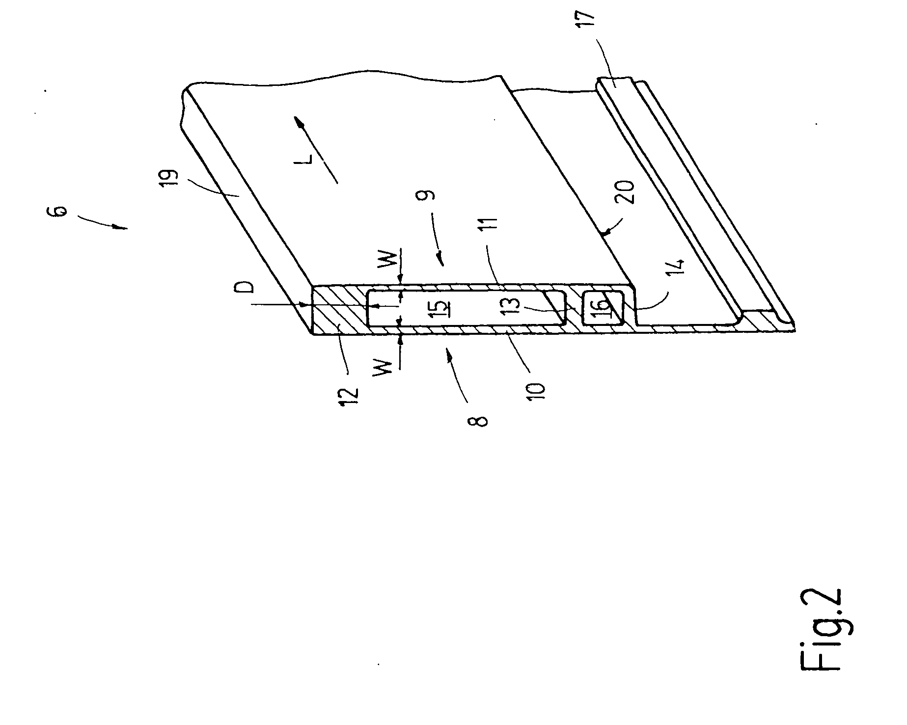
[0010] The shaft rod according to the invention has, in its first embodiment according to claim 1, a basic body provided with a web which is situated at its narrow side and in which a recess is formed. The recess preferably does not pierce the web; rather, it forms an only unilaterally open pocket which is surrounded by a wall on five sides. This may be achieved, for example, by providing that the depth of the recess formed in the web is less than the thickness of the web. The bottom which borders the elongated recess or pocket is not pierced. To make this possible even if reinforcing elements are to be provided, whose thickness is greater than the wall thickness of the basic body, the thickness of the respective web is preferably significantly greater than the wall thickness of the basic body at its flat sides. For example, the web may have an at least approximately
square cross section. The formation of a very massive web which permits the provision of deeper pockets, has the
advantage at the same time that the parts of the web remaining outside the recesses may constitute securing locations for other elements, such as driving elements.
[0014] In a modified embodiment which is the subject of claim 3, it is permissible that the recess for receiving the reinforcing element pierces the web. The web in this instance has a significantly greater thickness than the basic body of the shaft rod in its other portions. In this manner, externally of the reinforcing elements, the remaining thick web portions provide for the possibility of an attachment of external elements, such as driving elements. An attachment of reinforcing elements is possible at arbitrary locations. At the locations designed for attachment, the web is not removed, but remains available as a force-introducing location. At the remaining locations the web may be entirely or partially removed for providing receiving spaces for the reinforcing elements and for reducing the weight of the shaft rod.
[0016] Further, it is taken into consideration that the reinforcing element has a longitudinal sectional shape which equals that of the recess. This makes possible a five-sided gluing of the reinforcing element to the basic body. While such an arrangement is not a necessity, it is important that the recesses and, accordingly, also the ends of the reinforcing elements do not end abruptly in the length direction of the shaft rod. Rather, it is sought to allow the ends of the recess to run out gradually, by providing that the recesses end flattened in run-out zones. Accordingly, the ends of the reinforcing elements are preferably wedge shaped or ramp shaped. Such an arrangement avoids the occurrence of abrupt cross-sectional changes in the shaft rod and thus abrupt changes in the rigidity thereof. This prevents shaft rod breakages due to high dynamic stresses which otherwise would occur should the rigidity of the shaft rod change locally very substantially. The run-out of the recesses may be linear or arcuate. In this connection it is sought to design the length of the terminal zone to be minimum twice and maximum four times the depth of the recess. The longitudinal sectional shape of the recess and that of the reinforcing element agree with one another in the run-out zones, but they may differ from one another. The noted length of the run-out zone makes it possible, for example, to provide the recess with an arcuate end and the reinforcing element with a linearly extending, wedge shaped end, without risking disadvantages concerning rigidity.
[0017] In a preferred embodiment of the shaft rod which is defined in claim 15, the shaft rod is provided at its outer side with an Eloxal layer which increases its scratch resistance and reduces its tendency to
corrosion. The recess for receiving the reinforcing element, however, remains free from any Eloxal
coating. Nevertheless, an Eloxal layer may be present at the ends of the recess; it is less interfering there. This complies with the manufacturing reliability and the required strength of the shaft rod. It has been found that the adhesive bond between the reinforcing element and the basic aluminum body may be significantly improved by the absence of the Eloxal layer. Such conditions are obtained, for example, by first maintaining closed a hollow channel present in the extruded aluminum member, while providing the basic body with an Eloxal layer at its outer face. The
electrolyte acting on the basic aluminum body may possibly penetrate into the channels of the basic aluminum body, but an Eloxal layer will be formed at the most only on short regions at the ends. Web portions are removed only after completing the Eloxal process, to thus laterally open the hollow channel. Thus, in gluing in the reinforcing element, Eloxal-
free wall regions of the shaft rod are affected, where a firm adhesive joint is to be provided.
[0018] The process is even more reliable if first massive web regions are formed into which the desired recesses are milled following the Eloxal process. The thus-obtained recess has a non-oxidized wall to which reinforcing elements may be securely bonded by gluing.
[0021] By virtue of the three-sided gluing, very large adhesive surfaces are obtained which ensure a high reliability of the shaft rod which constitutes a rigid and deformation-
proof construction. It may be adapted flexibly and economically to the conditions and requirements of a specific weaving
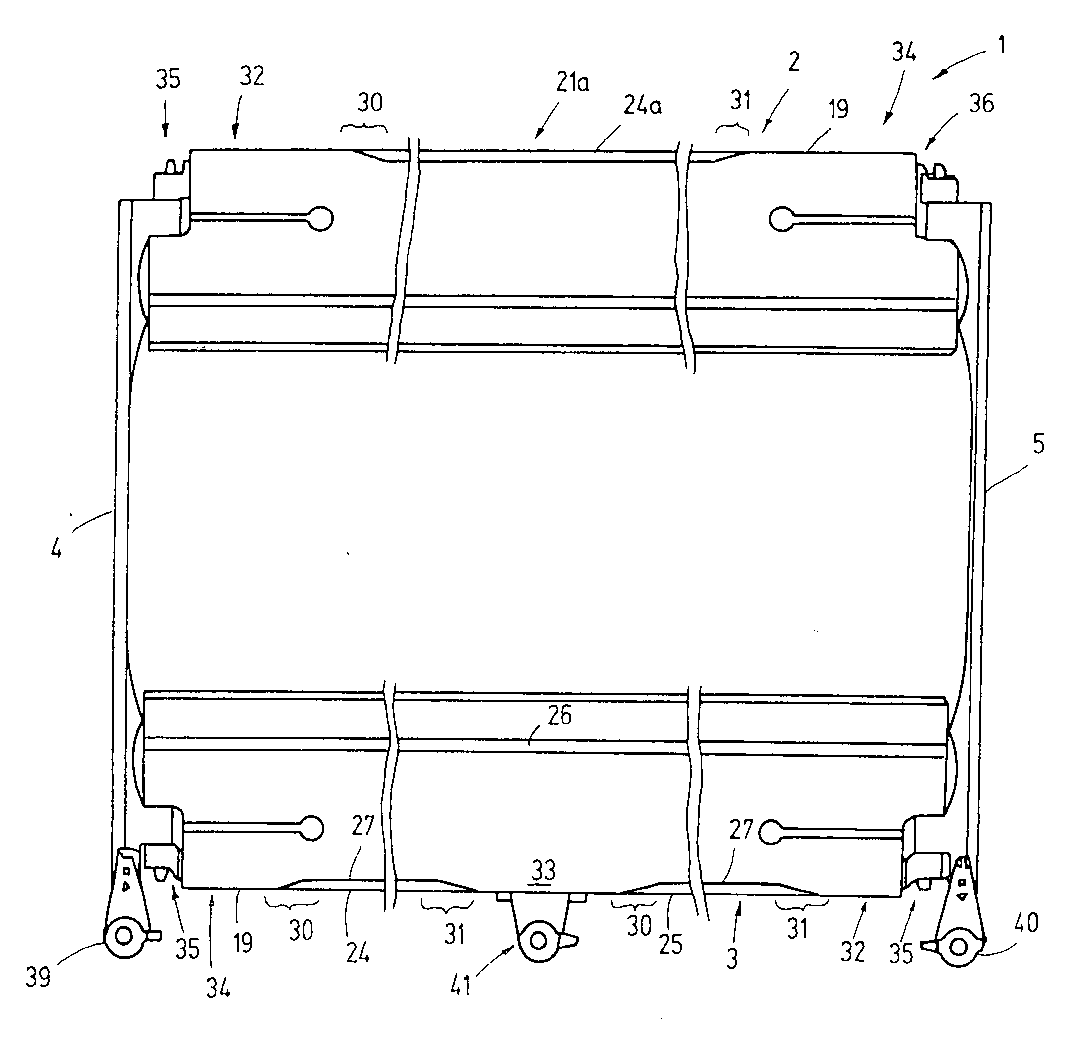
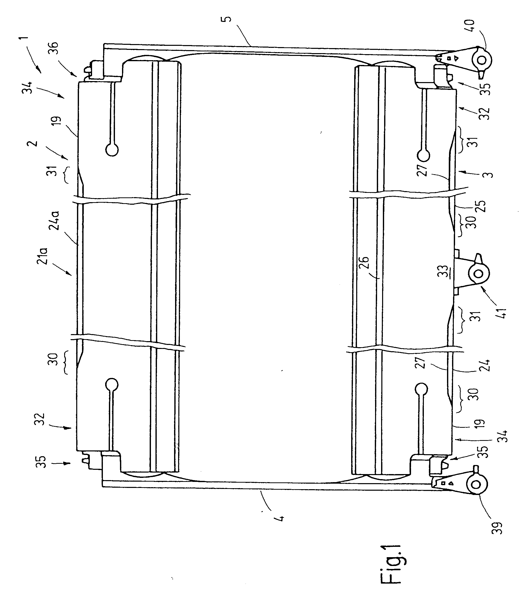
machine construction without the need of considering, to a greater extent, losses concerning strength properties. It is also feasible to structure only one shaft rod of the heald shaft, preferably the upper shaft rod, according to the invention and to use a conventional aluminum member for the lower shaft rod. Such a solution is particularly sensible in case several driving locations are present at the lower shaft rod. Based on the short, free bending length of the lower shaft rod, its extent of bending in such an application is maintained within limits. Applying expensive reinforcing elements to the lower shaft rod would not be sensible for economical considerations. In contrast, with the shaft rod according to the invention, if used as the upper shaft rod of the heald shaft, for large weaving width of, for example, in excess of 280 cm, no intermediate reinforcing braces are needed which would ensure the distance between the upper and the lower shaft rods. Such intermediate braces which always adversely affect the quality of the weave, may be dispensed with. The shaft rod according to the invention which serves as the upper shaft rod has a sufficient rigidity to maintain the extent of bending within acceptable limits despite the different bending lengths between the upper and the lower shaft rods. In this manner an economically particularly advantageous solution is obtained.
