
Heat exchanger with modified diffuser surface

a technology of heat exchanger and diffuser, which is applied in the direction of heat exchange apparatus, heat transfer modification, light and heating equipment, etc., can solve the problems of reducing heat exchange efficiency, reducing resistance to thermal fatigue, and often affecting the shape of packaging constraints, so as to improve the gas flow and thermal transfer efficiency of the heat exchanger, and minimize the formation of macro-boundary layers. , the effect of separation

Inactive Publication Date: 2007-03-22
HONEYWELL INT INC
View PDF19 Cites 32 Cited by
  • Summary
  • Abstract
  • Description
  • Claims
  • Application Information

AI Technical Summary

Benefits of technology

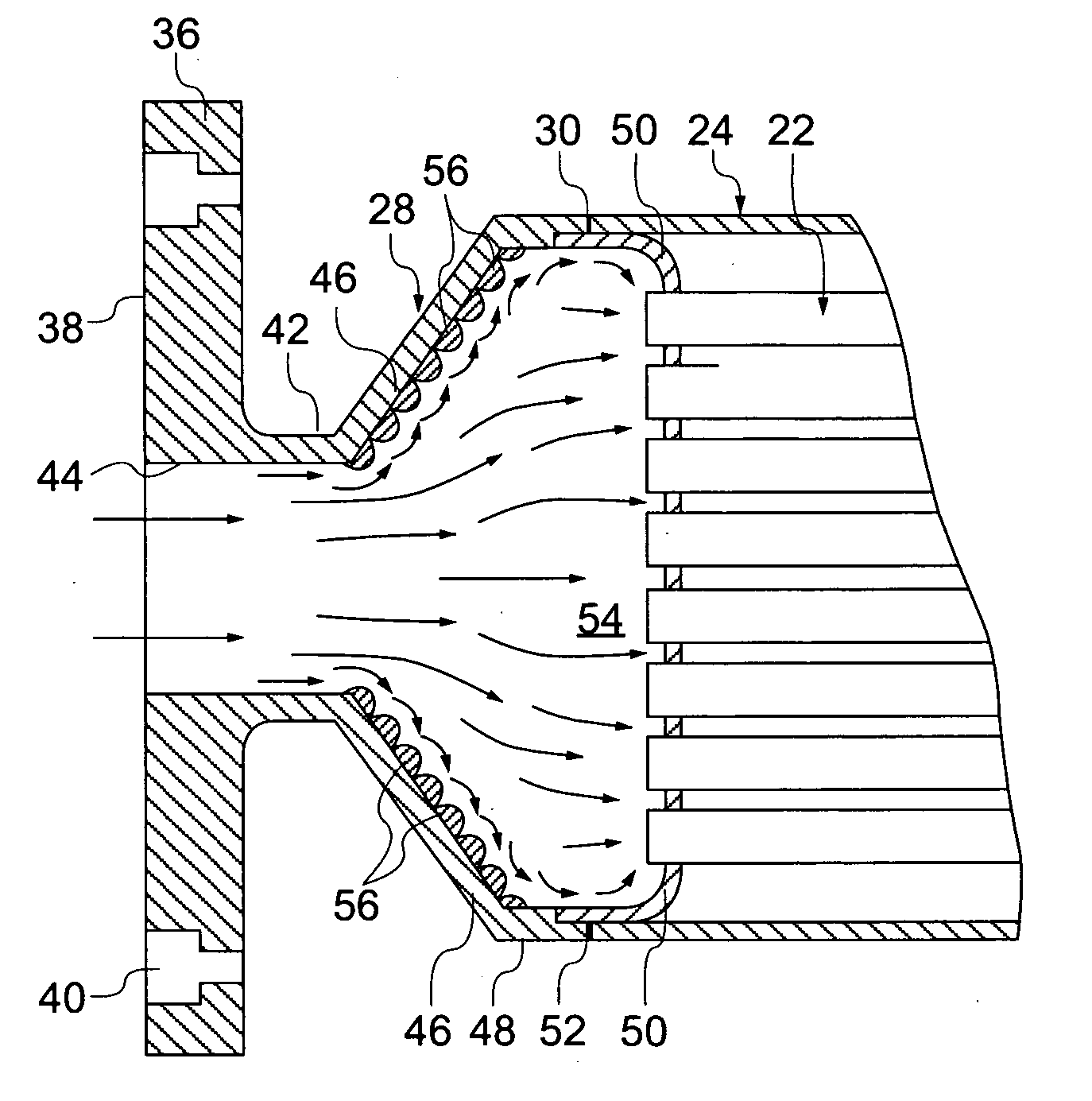
[0010] In an example embodiment, the individual surface features are projections that each project outwardly a distance from the inside surface and that are positioned along at least a region of the inside surface of the outwardly diverging wall section. In a preferred embodiment, the projections are provided in the form of rounded dimples, and occupy at least about 10 percent of the surface area of the outwardly diverging wall section. The projections can be provided in rows and arranged such that the projections in one row are staggered from the projections in an adjacent row so as to avoid straight line passage of gas through the row of projections.
[0011] Configured in this manner, the surface features in the diffuser operates to prevent the formation of a large gas recirculation zone along the inside wall surface, thereby minimizing the formation of macro-boundary layer has separations and improving the gas flow and thermal transfer efficiencies of the heat exchanger.

Problems solved by technology

In such applications, packaging constraints are often an issue for such heat exchangers, since the available space for such a heat exchanger proximate to the engine is often at a premium.
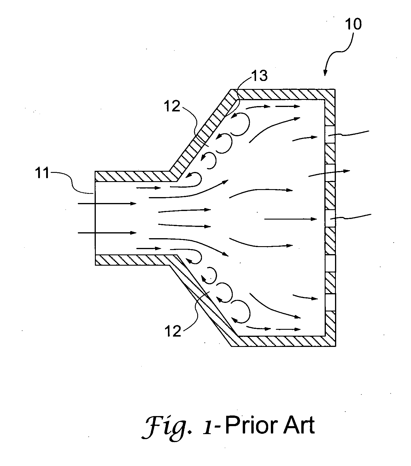
However, the use of such short diffusers are known to a create boundary layer separation of the gas flow entering the heat exchanger that operates to increase the pressure drop and disrupt the flow distribution of gas through the heat exchanger.
In some applications, such as high temperature exhaust gas coolers, the uneven flow distribution resulting from the use of such short diffusers can also cause a reduced resistance to thermal fatigue and reduced heat transfer efficiency.
The higher pressure drop through the heat exchanger as a result of such short diffusers can also result in less gas flow through the exchanger or higher fuel consumption to overcome the pressure drop.
This zone of eddy loses that occur along the wall surface create both a disruption of the gas flow and a pressure loss within the heat exchanger prior to entering the heat exchanger core or tube bundle.
In such attempts, however, the use of ribs or fins only affected the boundary separation perpendicular to the gas flow direction.
Additionally, the interior surfaces comprising the ribs or fins used in such attempts can be difficult and time consuming to manufacture.

Method used


Image

  • Heat exchanger with modified diffuser surface
  • Heat exchanger with modified diffuser surface
  • Heat exchanger with modified diffuser surface

Examples


Embodiment Construction

[0020] The present invention relates to heat exchangers used for reducing the temperature of an entering gas or fluid stream. The particular application for the heat exchangers of the present invention is with vehicles and, more particularly, to cool an exhaust gas stream taken from an internal combustion engine. However, it will be readily understood by those skilled in the relevant technical field that heat exchanger constructions of the present invention as described and illustrated herein are understood to be used in a variety of different applications, and thus the invention disclosed herein should not be limited to such applications

[0021] Generally, heat exchangers constructed in accordance with principles of this invention include a diffuser that has been specially engineered to have an inside wall surface configured with a plurality of surface features that are use to reduce or eliminate unwanted boundary layer separation of gas within the diffuser during heat exchanger ope...


PUM


Abstract

A diffuser comprising an inlet passage, an outwardly diverging sidewall, and an outlet. The inlet, outwardly diverging sidewall and outlet each have an inside surface that defines an interior through which a gas or fluid passes in a flow direction from the inlet to the outlet. Wherein at least a region of the inside surface includes a plurality of individual surface features that are configured to reduce or eliminate unwanted boundary layer separation of gas or fluid that passes thereover.

Description

FIELD OF INVENTION [0001] This invention relates generally to the field of heat exchangers and, more particularly, to heat exchangers that include a diffuser that is specially engineering having a modified inside surface to help control pressure loss and gas or fluid flow distribution within the heat exchanger. BACKGROUND OF THE INVENTION [0002] The present invention relates to heat exchangers that are generally configured comprising a number of internal fluid or gas passages disposed within a surrounding body. In an example embodiment, the internal passages are designed to accommodate passage of a particular fluid or gas in need of cooling, and the body is configured to accommodate passage of a particular cooling fluid or gas, i.e., coolant, used to reduce the temperature of the fluid or gas in the internal passage by heat transfer through the structure of the internal passages. A specific example of such a heat exchanger is one referred to as a shell and tube exchanger, which can ...

Claims


Application Information

Patent Timeline
IPC IPC(8): F28F9/02
CPCF28F9/02F28F2009/029F28F13/02F28F9/0263
Inventor AGEE, KEITH D.BELDAM, RICHARD P.DILLEY, ROLAND L.
Owner HONEYWELL INT INC
Learn More