Ink jet head nozzle plate manufacturing method, Ink jet head nozzle plate manufacturing apparatus, Ink jet head nozzle plate, Ink jet head, and Ink jet recording apparatus

Active Publication Date: 2007-03-22
SII PRINTEK
View PDF9 Cites 6 Cited by
  • Summary
  • Abstract
  • Description
  • Claims
  • Application Information

AI Technical Summary

Benefits of technology

[0029] a recording medium conveying portion, for conveying a recording medium onto which ink is discharged by the ink jet head. As a result, the quality of an image provided for the recording medium can be improved.
[0030] As is described above, according to the ink jet head nozzle plate manufacturing method of the invention, the laser beam can be condensed at multiple locations on the face of a nozzle plate, and a plurality of unif

Problems solved by technology

However, when the angle of the taper becomes too great, a resulting problem is that ink discharged from a nozzle will either fly transversely or air will be sucked into the nozzle following the discharge of ink.
Then, howev

Method used


Image

  • Ink jet head nozzle plate manufacturing method, Ink jet head nozzle plate manufacturing apparatus, Ink jet head nozzle plate, Ink jet head, and Ink jet recording apparatus
  • Ink jet head nozzle plate manufacturing method, Ink jet head nozzle plate manufacturing apparatus, Ink jet head nozzle plate, Ink jet head, and Ink jet recording apparatus
  • Ink jet head nozzle plate manufacturing method, Ink jet head nozzle plate manufacturing apparatus, Ink jet head nozzle plate, Ink jet head, and Ink jet recording apparatus

Examples


Embodiment Construction

[0041] The preferred embodiments of the present invention will now be described in detail.

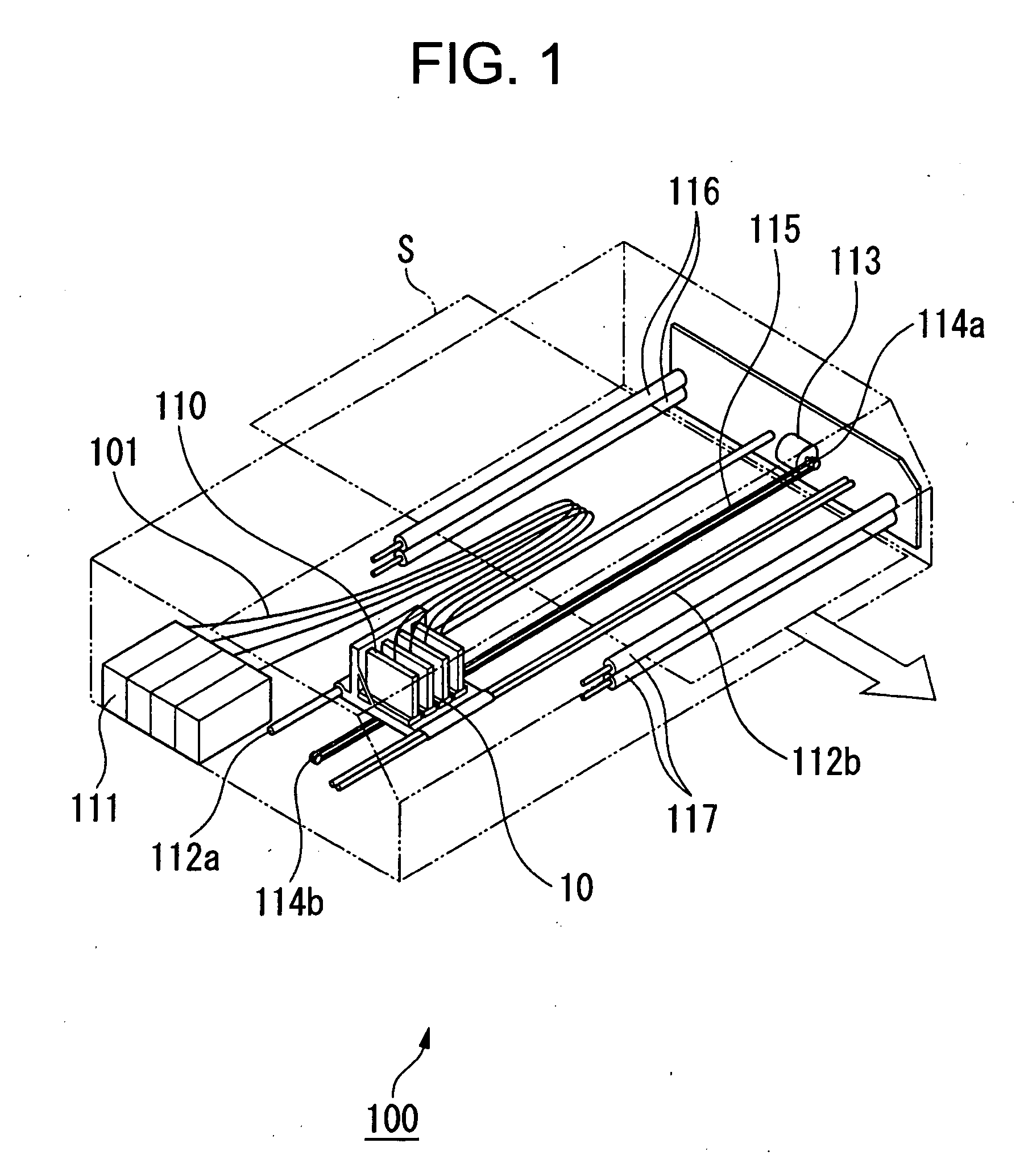
[0042]FIG. 1 is a schematic perspective view of an ink jet recording apparatus. As shown in FIG. 1, an ink jet recording apparatus 100 for this embodiment includes: a plurality of ink jet heads 10 provided for individual colors; a carriage 110, wherein the ink jet heads 10 are mounted, in parallel, in the main scanning direction; and ink cartridges 111, for supplying ink through ink supply tubes 101, which are flexible tubes. The carriage 110 reciprocates along a pair of guide rails 112a and 112b in the direction of their long axis. A drive motor 113 is located at one end of the guide rails 112a and 112b, and the drive force exerted by the drive motor 113 is transmitted to a timing belt 115 that is extended between a pulley 114a, which is connected to the drive motor 113, and a pulley 114b, which is located at the other end of the guide rails 112a and 112b. The carriage 110, fixed at a predete...


PUM


Abstract

A method for efficiently and stably manufacturing a nozzle plate wherein nozzle openings are accurately formed. According to an ink jet head nozzle plate manufacturing method for emitting a laser beam through lenses onto the face of a nozzle plate to form a plurality of nozzle openings, these lenses are a plurality of micro lenses arranged on the same plane, and the pitch for arranging the micro lenses that are adjacent in the direction in which the nozzle openings are formed in the nozzle plate is defined as an integer multiple of the pitch for arranging adjacent nozzle openings.

Description

BACKGROUND OF THE INVENTION [0001] 1. Field of the Invention [0002] The present invention relates to an ink jet recording apparatus that is applied, for example, for a printer or a facsimile machine, and to an ink jet head used for the ink jet recording apparatus, a nozzle plate used for the ink jet head, an apparatus for manufacturing the nozzle plate and a method for manufacturing the nozzle plate. [0003] 2. Related Background Art [0004] An ink jet recording apparatus is known that records characters and images on a recording medium by employing an ink jet head wherein a plurality of ink chambers, made of a piezoelectric material for which a poling process has been performed, are arranged in parallel, and electrodes are mounted on two inner walls of the individual ink chambers, and wherein the piezoelectric material is deflected by selectively transmitting a drive pulse signal to these electrodes, and to thus discharge ink from a plurality of nozzle openings that communicate with ...

Claims


Application Information

Patent Timeline
IPC IPC(8): B41J2/16B23K26/382B41J2/135B41J2/14B41J2/145
CPCB23K26/0676B41J2/1609B41J2/1634B41J2/1623B41J2/1632B41J2/162B23K26/06B23K26/08
Inventor HARAJIRI, TOSHIHIKO
Owner SII PRINTEK
Why Eureka
Try Eureka