Liquid transporting apparatus, actuator unit, and method of producing liquid transporting apparatus

a technology of actuators and liquid transporting devices, which is applied in the direction of printing, etc., can solve the problems of disengagement or breakage of electric connections, damage to piezoelectric sheets, and difficulty in filling adhesives,

Active Publication Date: 2007-03-22
BROTHER KOGYO KK
View PDF4 Cites 14 Cited by
  • Summary
  • Abstract
  • Description
  • Claims
  • Application Information

AI Technical Summary

Benefits of technology

[0043] Accordingly, by a simple method of forming the wiring section in which the first through hole and the second through hole are formed, arranging the wiring section such that the first through hole and the connecting area of the first electrode overlap, jetting the liquid droplet of the electroconductive material toward the first through hole and curing the jetted liquid droplet of the electroconductive material, and jetting the liquid droplet of the fixing material toward the second through hole and curing the jetted liquid droplet of the fixing material, it is possible to electrically connect the first wiring and the electrode, and to mechanically connect the substrate and the piezoelectric layer. Further, it is possible to electrically and mechanically connect the substrate of the wiring section and the piezoelectric layer of the piezoelectric actuator without applying a pressure to the piezoelectric layer. Therefore, it is possible the piezoelectric layer from being damaged. Furthermore, since the piezoelectric layer and the substrate are mechanically connected by the fixing material, the electric

Problems solved by technology

US 2005/0041074 A1, when the pads of the FPC are bonded to the individual electrodes or the common electrode of the piezoelectric sheet by thermo compression bonding, it is necessary to apply a high pressure so as to compensate for a variation in the height among the contact-point land portions, and thus there is a fear that the piezoelectric sheet is damaged by the pressure.
Further, since the piezoelectric sheet and the FPC are connected only at a portion of the electric connection, when an external pressure is exerted to the FPC, there is also a fear that the electric connection is disengaged or broken.
However, the filling of adhesive complicates the structure.
Further, in a piezoelectric actuator which underg

Method used


Image

  • Liquid transporting apparatus, actuator unit, and method of producing liquid transporting apparatus
  • Liquid transporting apparatus, actuator unit, and method of producing liquid transporting apparatus
  • Liquid transporting apparatus, actuator unit, and method of producing liquid transporting apparatus

Examples


first embodiment

[0079] A first embodiment according to the present invention will be described below with reference to the diagrams. The first embodiment is an example in which the present invention is applied to an ink-jet head which perform recording on a recording paper by discharging ink from a nozzle.

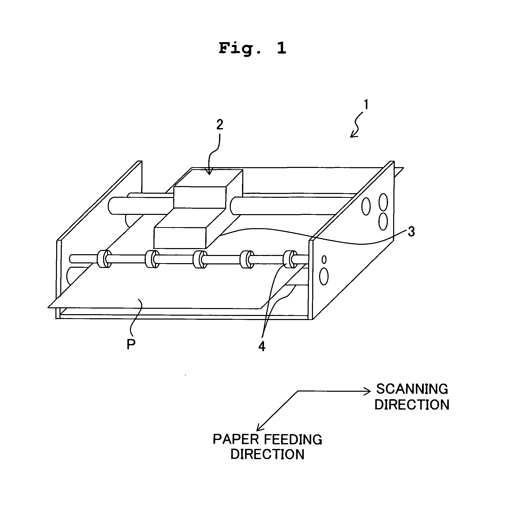
[0080]FIG. 1 is a schematic perspective view of an ink-jet printer 1 according to the first embodiment. As shown in FIG. 1, the ink-jet printer 1 includes a carriage 2 which is movable in a left and right direction (scanning direction) in FIG. 1, an ink-jet head 3 of a serial type which is provided to the carriage 2 and discharges ink onto a recording paper P, and transporting rollers 4 which transport or carry the recording paper P in a paper feeding direction (forward direction in FIG. 1). The ink-jet head 3, while moving integrally with the carriage 2 in the scanning direction, records an image and / or a character (hereinafter referred simply as “image”) by discharging ink onto the recording pa...

first modified embodiment

[0109] As a first example of the first modified embodiment, as shown in FIGS. 8 and 9, projections 60 made of an epoxy resin and projecting upward may be formed on a surface of the piezoelectric layer 41 in areas each of which is between the adjacent pressure chambers 10 in the paper feeding direction and which does not overlap with one of the pressure chambers 10. In this case, gaps are defined, due to the projections 60, between the piezoelectric layer 41 and the FPC 33, in areas of the piezoelectric layer 41 overlapping in a plan view with the pressure chambers 10 respectively. Due to the gaps, the piezoelectric layer 41 and the FPC 33 are prevented from making a contact with each other. Accordingly, it is possible to prevent the FPC 33 from making a contact with the area or areas of the piezoelectric layer 41 in the area overlapping with the pressure chamber or chambers 10, and affecting discharge characteristics of ink. It is possible to form such projections by performing a st...

second modified embodiment

[0111] As shown in FIG. 11, a dummy electrode 17 which is insulated from the individual electrode 12, may be formed in an area of the piezoelectric layer 41, the area overlapping with one of the through holes 42b in a plan view, and an electroconductive material 49 may be filled in the through hole 42b. Even in this case, the piezoelectric layer 41 and the substrate 42 are mechanically connected by the electroconductive material 49. Here, since the electroconductive material 49 is joined to the dummy electrode 17 formed on the surface of the piezoelectric layer 41, the joining strength is enhanced as compared to a case in which the electroconductive material 49 is filled in the through hole 49b without forming the dummy electrode 17. Furthermore, when the electroconductive material 49 and the electroconductive material 44 are made of the same material, it is possible to form the electroconductive material 44 and the electroconductive material 49 in the same step, and then to cure th...


PUM


Abstract

A piezoelectric layer with an individual electrode and a contact point formed thereon, and an FPC having a substrate on which a wiring is formed are in this order arranged on a surface of a channel unit having a pressure chamber. A first through hole is formed in an area, of the substrate, overlapping in a plan view with the contact point, and a second through hole is formed in another area, of the substrate, not overlapping in a plan view with the pressure chamber. An electroconductive material is filled in the first through hole, and a fixing material is filled in the second through hole. Accordingly, it is possible to electrically connect the individual electrode and the wiring of the FPC, and to mechanically connect the piezoelectric layer and the substrate of the FPC.

Description

CROSS REFERENCE TO RELATED APPLICATION [0001] The present application claims priority from Japanese Patent Application No. 2005-216706, filed on Jul. 27, 2005, the disclosure of which is incorporated herein by reference in its entirety. BACKGROUND OF THE INVENTION [0002] 1. Field of the Invention [0003] The present invention relates to a liquid transporting apparatus which transports a liquid, an actuator unit, and a method of producing the liquid transporting apparatus. [0004] 2. Description of the Related Art [0005] An ink-jet head in which a common electrode or an individual electrode formed on an upper surface of a piezoelectric actuator and a wiring of an FPC (flexible printed circuit) arranged above the piezoelectric actuator are electrically connected is an example of an ink-jet head in which pressure is applied to the ink in a pressure chamber by the piezoelectric actuator to discharge ink from a nozzle communicating with the pressure chamber. For example, in an ink-jet head...

Claims


Application Information

Patent Timeline
IPC IPC(8): B41J2/05
CPCB41J2/14233B41J2002/14491B41J2002/14266
Inventor SUGAHARA, HIROTO
Owner BROTHER KOGYO KK
Why Eureka
Try Eureka