Pressure damping ink filter

a technology of ink filter and pressure damping, applied in printing and other directions, can solve the problems of improper charge of ink droplets, device failure, bad image formation, etc., and achieve the effect of reducing pressure fluctuations and avoiding improper charg

Inactive Publication Date: 2007-03-22
VIDEOJET TECH INC
View PDF7 Cites 15 Cited by
  • Summary
  • Abstract
  • Description
  • Claims
  • Application Information

AI Technical Summary

Benefits of technology

[0008] Embodiments of the present invention relate to a pressure damping ink filter for use with an ink jet printer. Ink from an ink system, such as an ink cartridge, is drawn into the input portion of an electric pump. The ink is then pressurized before exiting through the output portion of the pump and on towards the pressure damping ink filter. The pressure damping ink filter may include a filter medium positioned in a filter housing and at least one flow control member. The filter medium may remove undesirable debris and / or contaminants from the ink. The flow control member, in combination with any pressure damping provided by the thickness of the filter medium and the ink volume capacity of the filter housing, may substantially reduce, if not eliminate, pressure fluctuations that are generated by the high frequency electric pump. The flow control member, such as fixed or variable input and output restrictors, may be located inside and / or outside the filter housing. Further, the flow control member may be molded as part of the filter housing and / or part of the filter medium itself.

Problems solved by technology

A shift in position in the charging field may result in the ink droplets receiving an improper charge, i.e. an insufficient or excessive charge.
The improperly charged ink droplets may then be misdirected by the deflection electrodes, thereby causing the ink to be deposited at an unintended location on either the substrate, which may result in a bad image formation, or on print-head components, which may eventually cause a device failure, such as a high voltage, no signal, or phasing fault.
One common problem of conventional ink jet printers is that the electrical fluid pumps that are used to pressurize the ink stream may generate high frequency pulses, i.e. pressure surges.
However, the relatively large size of the filter medium and volume of ink required may reduce the effectiveness of these systems, and may also increase operating and construction costs.
Further, the large ink volume in these systems increases the chances that a greater portion of ink will go unused before its period of usefulness expires, in which case larger volumes of unused ink may be wasted.
However, the moving parts of such pressure damper devices may be damaged and / or fail as their components come in contact with the ink or other fluids.
Further, over a period of time, these moving parts may also degrade, which may result in a reduction in the pressure damper device's ability to effectively maintain the desired pre-set operating ink pressure.
These pressure damper devices are also often relatively large in size and costly.

Method used


Image

  • Pressure damping ink filter
  • Pressure damping ink filter
  • Pressure damping ink filter

Examples


Embodiment Construction

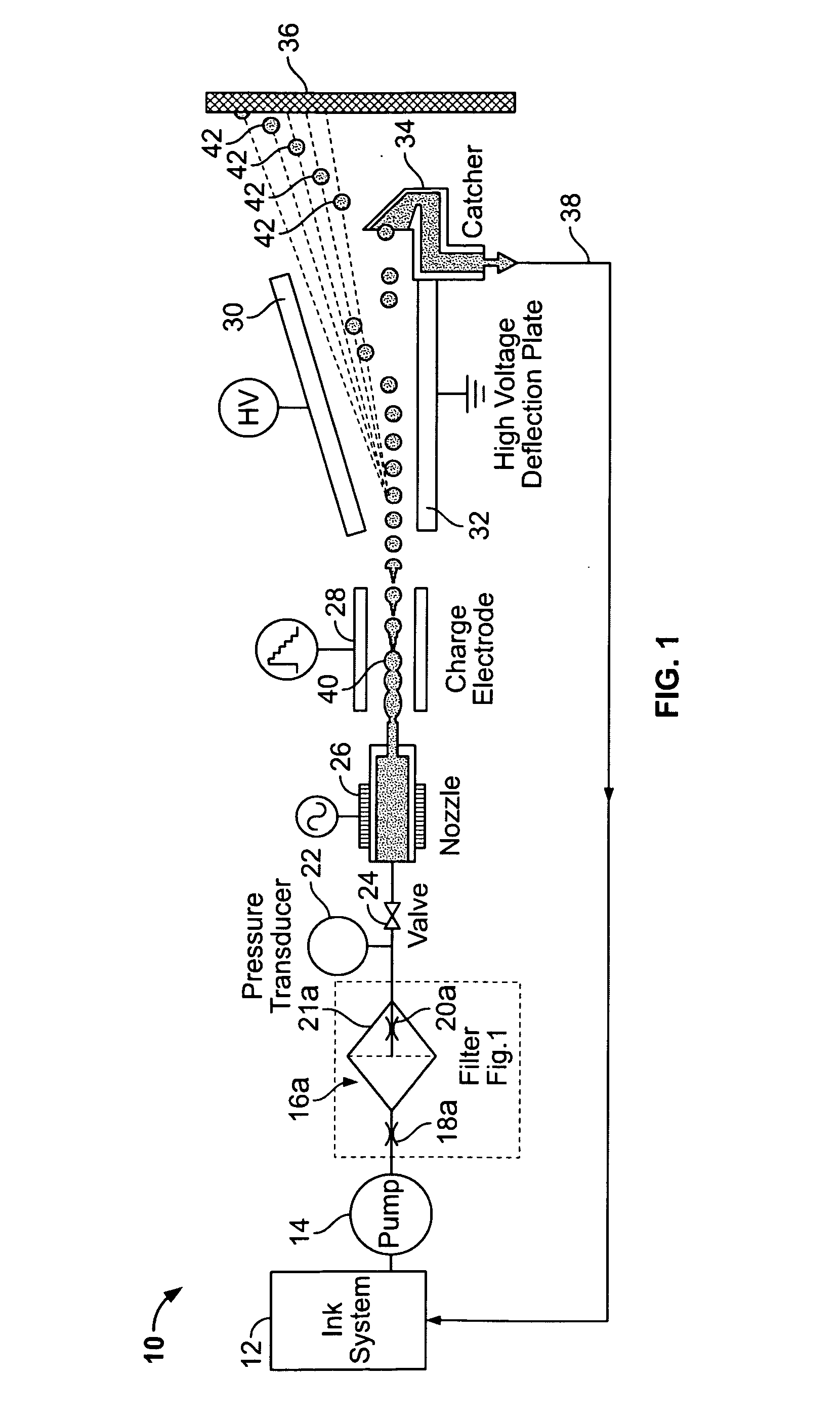
[0020]FIG. 1 illustrates a continuous ink jet printer 10 having a pressure damping ink filter 16 according to an embodiment of the present invention. As shown, ink from an ink system 12, such as an ink cartridge, is drawn into the input portion of a pump 14, such as an electrical gear pump. Once inside the pump 14, the ink may be pressurized before exiting through the output of the pump 14.

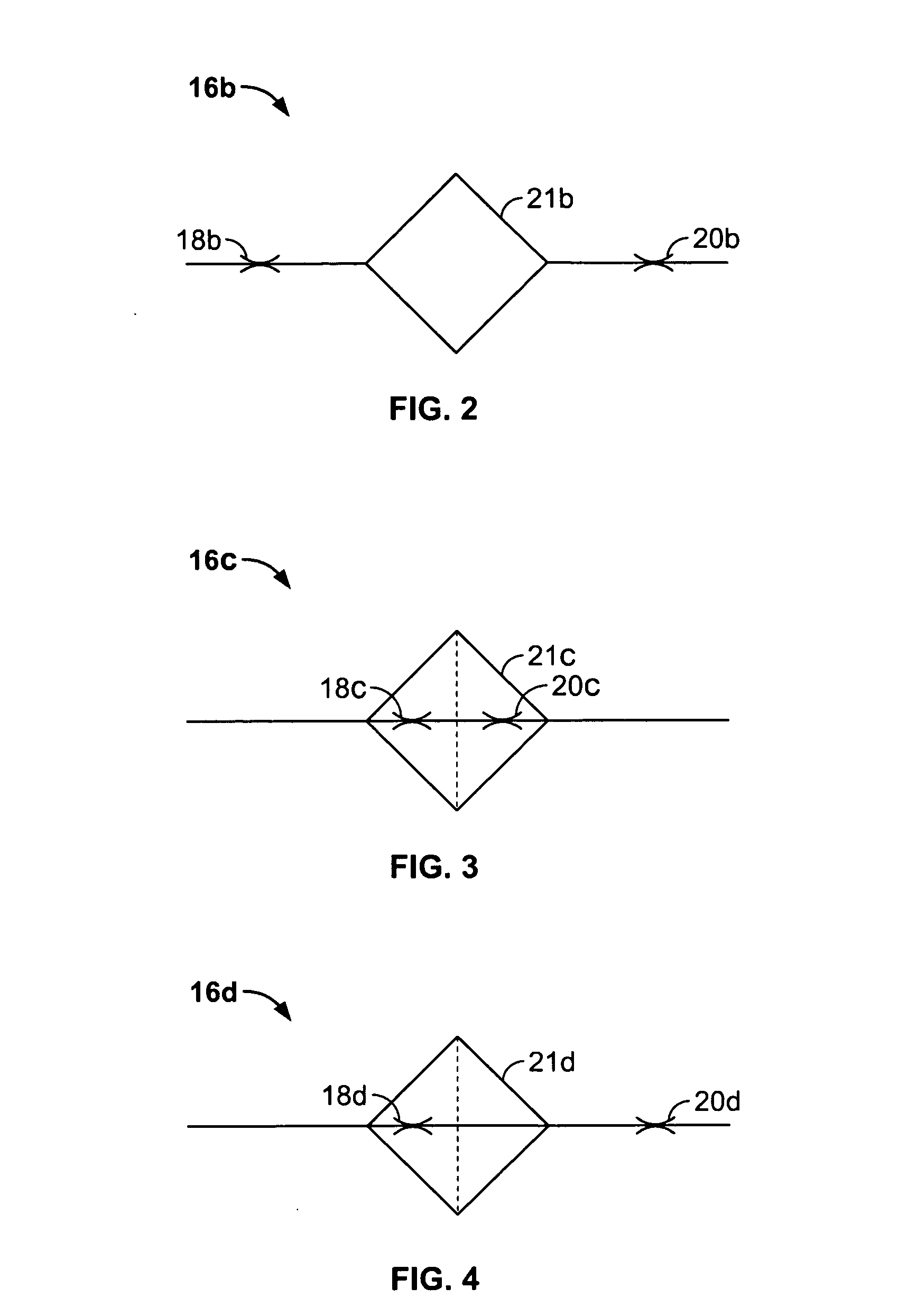
[0021] After exiting the output of the pump 14, the ink may pass onto the pressure damping ink filter 16a. The pressure damping ink filter 16a may include at least one flow control member, such as an input restrictor 18a or an output restrictor 20a, and a filter housing 21a. The filter housing 21a may house a filter medium that may remove undesirable debris and / or contaminants from the ink.

[0022] The flow control member, such as a variable or fixed restrictor, may restrict or regulate the flow rate of ink that passes into, or out of, the filter housing 21a. By controlling the flow rate of the in...


PUM


Abstract

Embodiments of the present invention relate to a pressure damping ink filter for use with an ink jet printer. The pressure damping ink filter includes at least one flow control member and a filter. The flow control member, in combination with any pressure damping provided by the thickness of the filter medium and the ink volume capacity of the filter housing, may substantially reduce, if not eliminate, pressure fluctuations in the ink stream that are generated by a high frequency electric pump. The flow control member may be a fixed or variable input restrictor and a fixed or variable output restrictor. The input restrictor and/or output restrictor may also be located inside or outside of the filter housing. Further, the input and output restrictors may be molded as part of the filter housing or the filter itself.

Description

BACKGROUND OF THE INVENTION [0001] Embodiments of the present invention relate to printing, and particularly to a pressure damping ink filter for use in a continuous ink jet printer. [0002] Continuous ink jet printers are well known in the field of industrial coding and marking, and are widely used for printing information, such as expiry dates, on various types of substrates passing by the printer on production lines. Ink jet printing allows ink to be deposited or printed at pre-determined locations on a substrate so as to create desired images, shapes, forms, or characters, without requiring physical contact between the printing device and the substrate. [0003] Conventional ink jet printers may include an ink source, an electric fluid pump, an orifice or orifices (nozzles), a charging tunnel, and deflection electrodes. The ink may be pressurized by the electric fluid pump, which draws the ink from the ink source and pushes the ink through the nozzle. The ink droplets may then be d...

Claims


Application Information

Patent Timeline
Patent Type & Authority Applications(United States)
IPC IPC(8): B41J2/17
CPCB41J2/02
Inventor MURAD, GEORGEEREMITY, FRANK
Owner VIDEOJET TECH INC
Why Eureka
Try Eureka