
Autofocus control apparatus and method of controlling the same

a control apparatus and autofocus technology, applied in the direction of camera focusing arrangement, printers, instruments, etc., can solve the problems of difficult to accurately detect the skin color area, difficult to accurately detect the object, and inability to accurately focus the skin color area in some cases, so as to achieve accurate focusing

Inactive Publication Date: 2007-03-22
FUJIFILM CORP
View PDF3 Cites 66 Cited by
  • Summary
  • Abstract
  • Description
  • Claims
  • Application Information

AI Technical Summary

Benefits of technology

[0006] An object of the present invention is to relatively accurately allow focusing.
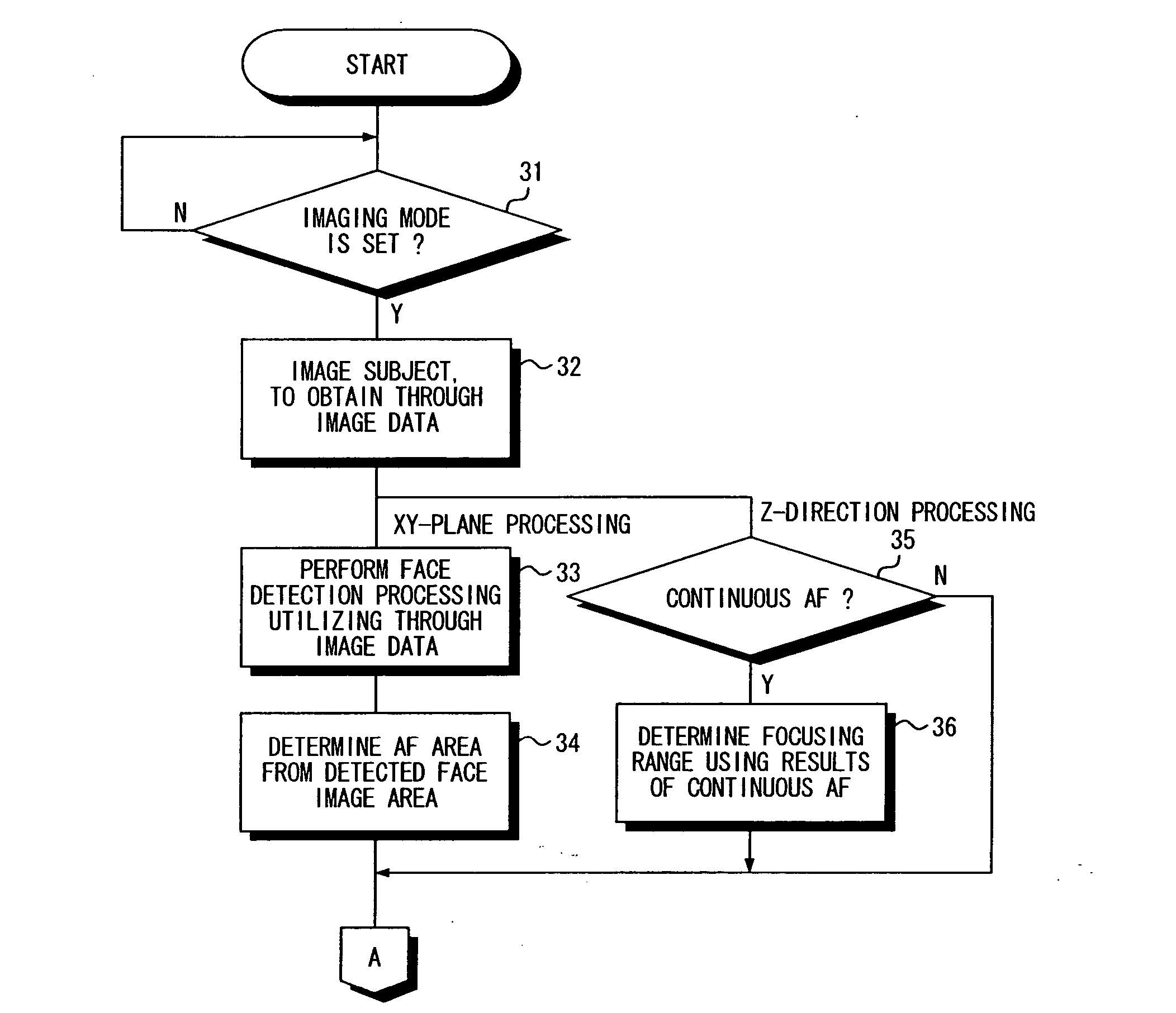
[0015] The autofocus control apparatus may further comprise a focusing range determination device that determines a focusing range in which the imaging lens moves under the control of the position control device on the basis of the through image data outputted from the solid-state electronic imaging device under the control of the third control device. Since the imaging lens moves within the focusing range, the position of the imaging lens can be controlled relatively quickly.
[0047] The position control device may control the position of the imaging lens on the basis of a value obtained by the weighted average of the plurality of distances.
[0055] The position control device may move the imaging lens a predetermined distance at a time toward the INF side from the NEAR side, detects the level of a desired frequency band component of the data corresponding to the object area obtained by imaging the subject for each movement position, and put the imaging lens at a position where the maximal value is first given.

Problems solved by technology

Even in a case where a skin color area is detected, however, it is difficult to accurately detect the skin color area when a subject image itself whose skin color should be detected is extremely defocused.
Therefore, the skin color area cannot, in some cases, be accurately focused even as a focusing area.
When an object is extremely defocused, it is difficult to accurately detect the object.

Method used


Image

  • Autofocus control apparatus and method of controlling the same
  • Autofocus control apparatus and method of controlling the same
  • Autofocus control apparatus and method of controlling the same

Examples


Embodiment Construction

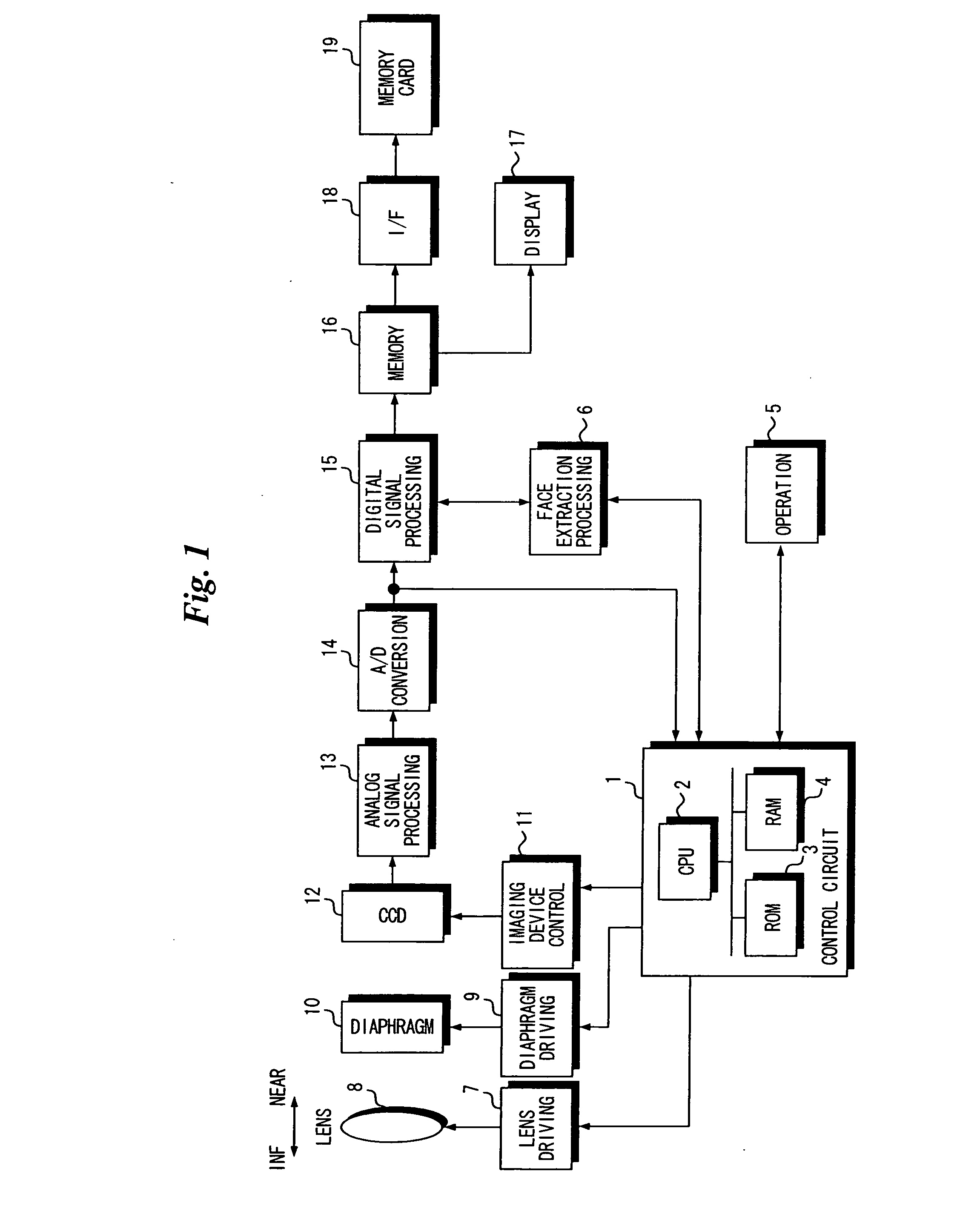
[0104]FIG. 1 is a block diagram showing the electrical configuration of a digital still camera according to an embodiment of the present invention.

[0105] The digital still camera according to the present embodiment is so adapted that a face portion of a subject is suitably focused.

[0106] The overall operation of the digital still camera is supervised by a control circuit 1. The control circuit 1 comprises a CPU 2, a ROM 3 storing an operation program of the digital still camera, predetermined data, and so on, and a RAM 4 temporarily storing data.

[0107] The digital still camera is provided with an operation device 5 comprising a mode setting switch for setting a mode such as an imaging mode or a reproduction mode, a button such as a shutter release button, and a switch. An operation signal outputted from the operation device 5 is fed to the control circuit 1.

[0108] A diaphragm 10 and an imaging lens 8 are provided ahead of a CCD 12. The imaging lens 8 is supported so as to be mov...


PUM


Abstract

When an imaging mode is set, a subject is imaged, and image data representing a subject image is obtained. Continuous AF is operated such that the subject image represented by the obtained image data is focused. Ranges ahead of and behind the focusing position of an imaging lens obtained in the continuous AF are determined as a focusing range. A formal search is conducted in the determined focusing range. A focusing position is determined from a graph of focusing integrated values obtained in the formal search. The imaging lens is put at the determined focusing position.

Description

BACKGROUND OF THE INVENTION [0001] 1. Field of the Invention [0002] The present invention relates to an autofocus control apparatus and a method of controlling the same. [0003] 2. Description of Background Art [0004] A skin color area included in a subject image is detected, and the detected skin color area is taken as a focusing area (see JP-A-11-146405). [0005] Even in a case where a skin color area is detected, however, it is difficult to accurately detect the skin color area when a subject image itself whose skin color should be detected is extremely defocused. Therefore, the skin color area cannot, in some cases, be accurately focused even as a focusing area. The same is true for a case where an object is detected from only light and dark (gradation) information without using color information. When an object is extremely defocused, it is difficult to accurately detect the object. SUMMARY OF THE INVENTION [0006] An object of the present invention is to relatively accurately all...

Claims


Application Information

Patent Timeline
IPC IPC(8): G03B13/00
CPCG03B13/36H04N5/23219H04N5/23212G06K9/00248G06V40/165H04N23/675H04N23/673H04N23/61H04N23/611H04N23/635
Inventor SUGIMOTO, MASAHIKO
Owner FUJIFILM CORP
Learn More